
DC power supply

a power supply and dc technology, applied in the direction of dc-dc conversion, power conversion systems, climate sustainability, etc., can solve the problems of surge voltage exceeding the voltage of the device, affecting other electronic devices, and destroying devices, so as to reduce the noise of the electric motor and reduce the supply power

Active Publication Date: 2012-11-29
HITACHI LTD +1
View PDF6 Cites 20 Cited by
  • Summary
  • Abstract
  • Description
  • Claims
  • Application Information

AI Technical Summary

Benefits of technology

[0019]According to the present invention, due to the snubber circuit composed of the snubber diode serving as the diode bridge connected in parallel to the filter capacitor and the snubber capacitor for connecting an output at an intermediate point of the diode bridge of the snubber diode serving as the diode bridge to the DC output side of the diodes of the rectifier circuit, the surge voltage generated during power recovery of the diodes of the rectifier circuit can be reduced and thus the electromagnetic noise can be also reduced.
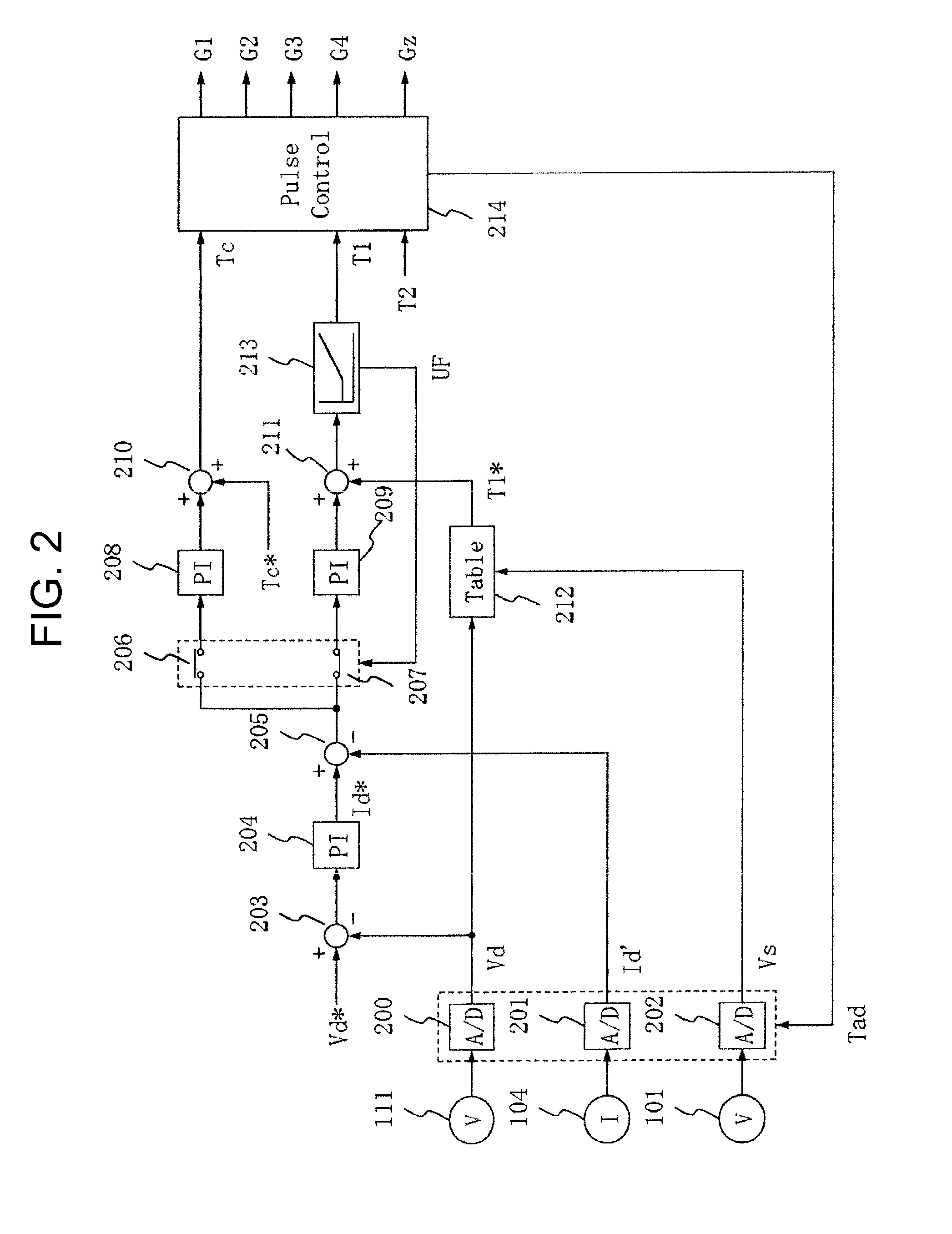
[0020]Since the current sensor for the secondary current of the transformer is provided and sampling and holding are performed by inputting an output signal from the current sensor in synchronization with the operating frequency of the converter after ½ of the resonant cycle obtained by the electrostatic capacitance of the snubber capacitor and the circuit inductance from turn-on of the converter and before ¾ of the resonant cycle obtained from the electrostatic capacitance of the resonant capacitor and the circuit inductance from turn-off, the load current can be correctly estimated from the secondary current.
[0021]Since the first controlling means for adjusting the supplied power by adjusting the gate pulse width in accordance with the sensor input while the operating frequency of the converter is maintained constant and the second controlling means for adjusting the supplied power by adjusting the operating frequency of the converter in accordance with the sensor input while the gate pulse width of the converter is maintained constant are provided, the supplied power can be reduced when the load is light.

Problems solved by technology

When the surge voltage is intensely generated as shown in FIG. 10, the surge voltage may exceed a device withstanding voltage and the devices may be destroyed.
Even when the surge voltage does not exceed the device withstanding pressure, an electromagnetic noise of a high frequency may be generated, and accordingly, other electronic devices may be negatively affected.
For example, they may be electromagnetically interfered.
The first problem is how to reduce the surge voltage of the diodes constituting the rectifier circuit 105 during the power recovery.
The problem here is, however, how to correctly estimate the load current Id from the secondary current I2 for saving the cost and recognize the correct load state without the current sensor for detecting the load current Id.
The third problem is how to perform the smooth control when the load is light.
Thus, it is difficult to reduce the supplied electric power.

Method used


Image

  • DC power supply
  • DC power supply
  • DC power supply

Examples


first embodiment

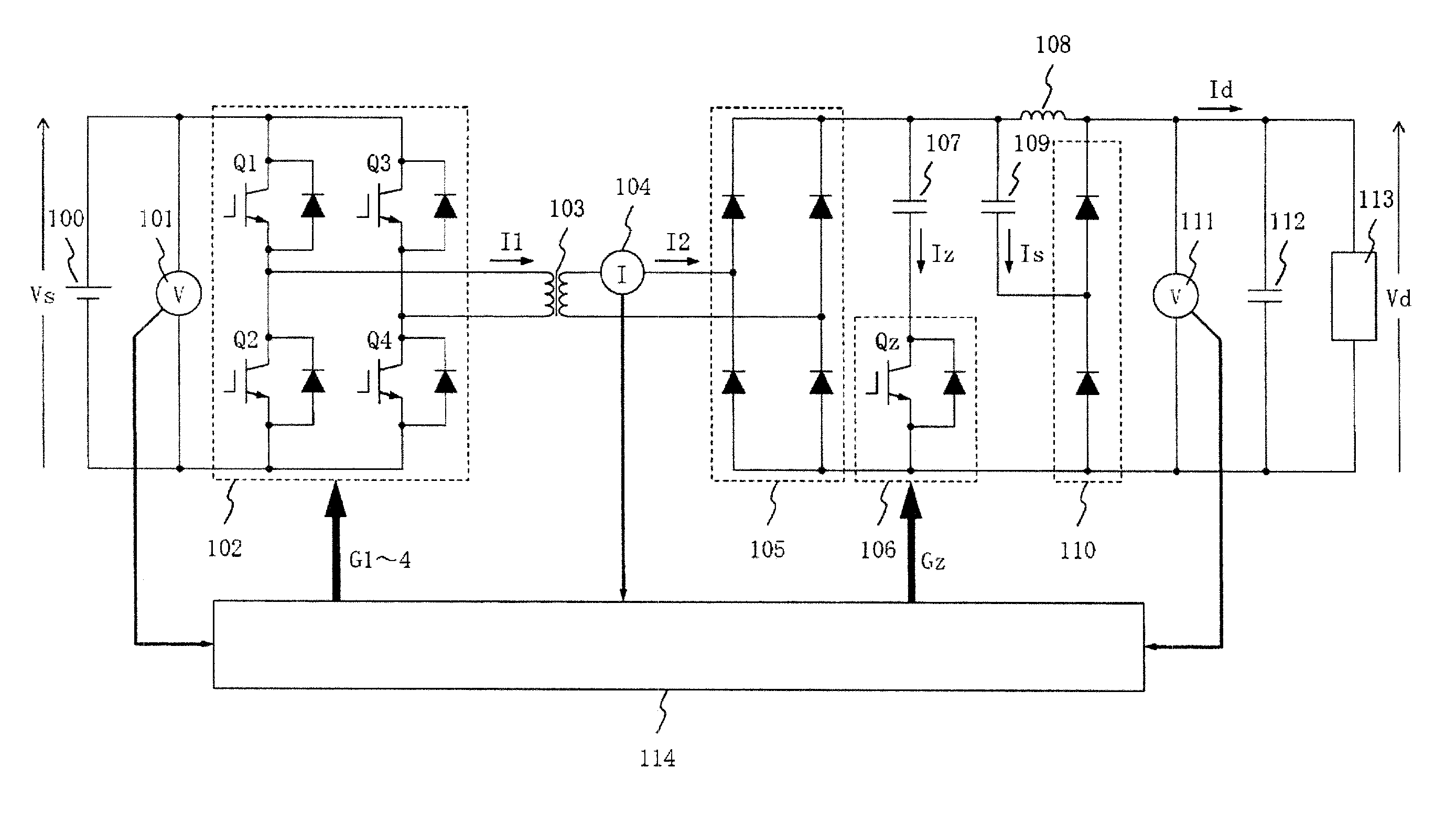
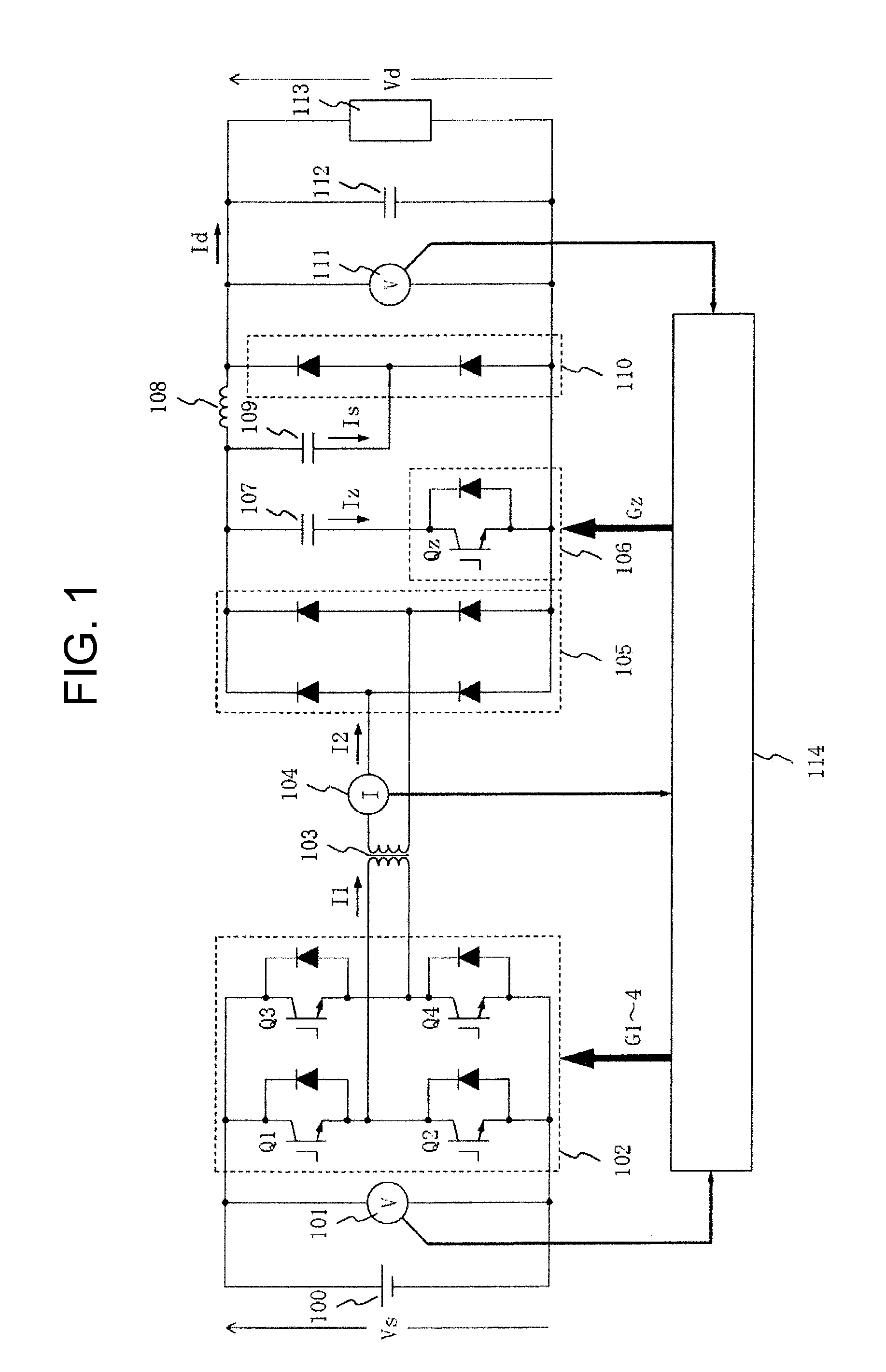
[0033]FIG. 1 shows an embodiment of the present invention. A DC power supply shown in FIG. 1 includes: a DC voltage source 100; a first voltage sensor 101 for detecting a DC input voltage Vs as an output voltage of the DC voltage source 100; a converter 102 for converting DC power outputted from the DC voltage source 100 into AC power; a transformer 103 for inputting the AC power outputted from the converter 102; a current sensor 104 for detecting a secondary current I2 of the transformer 103; a rectifier circuit 105 for converting the AC power outputted from the transformer 103 into DC power; a resonant circuit which is composed of a resonant switch 106 and a resonant capacitor 107 and connected in parallel to a DC output side of the rectifier circuit 105; a filter reactor 108 and filter capacitor 112 for smoothing the DC power outputted from the rectifier circuit 105; a snubber diode 110 serving as a diode bridge connected in parallel to the filter capacitor 112; a snubber capacit...


PUM


Abstract

A DC power supply including a resonant circuit on a secondary side of a transformer suppresses a surge voltage during power recovery of diodes constituting a rectifier circuit, correctly estimates a load current from a secondary current of the transformer, and adjusts supplied power when a load is light. The DC power supply includes a DC voltage source, a converter, a transformer, a rectifier circuit, a resonant circuit composed of a resonant switch and a resonant capacitor, a filter reactor, a filter capacitor, a snubber diode, a snubber capacitor, a load, first and second voltage sensors, a current sensor, and a controller for controlling gate pulses of semiconductor devices constituting a converter and the resonant switch and a signal for adjusting operation timings of A / D converters converting the signals of these sensors.

Description

[0001]The present application is based on and claims priority of Japanese patent application No. 2011-116758 filed on May 25, 2011, the entire contents of which are hereby incorporated by reference.BACKGROUND OF THE INVENTION[0002]1. Field of the Invention[0003]The present invention relates to a DC power supply using semiconductor devices. More specifically, the present invention relates to a soft-switching DC power supply including a resonant circuit for reducing switching losses in semiconductor devices.[0004]2. Description of the Related Art[0005]A power supply for converting direct current to direct current (hereinafter referred to as a DC power supply) is used to stabilize unstable direct current voltage, change direct current voltage, or provide electric isolation between input and output. Especially, in a DC power supply for providing electric isolation between input and output, a method of downsizing an isolation transformer by increasing an applied frequency is known.[0006]...

Claims


Application Information

Patent Timeline
IPC IPC(8): H02M3/335
CPCY02B70/1433H02M3/33576Y02B70/10H02M3/28
Inventor KOJIMA, TETSUONOZAKI, YUICHIROMAKINO, MASAFUMISHINOMIYA, TAKESHISUGIURA, TETSU
Owner HITACHI LTD
Learn More