Low Power Consumption, Long Range, Pluggable Transceiver, Circuits and Devices Therefor, and Method(s) of Using the Same

a technology of optoelectronic conversion and power consumption, applied in electromagnetic transceivers, gas-filled discharge tubes, solid cathodes, etc., can solve the problems of dml laser drivers consuming about half the power of eml laser drivers, and conventional transceivers also always consume power, so as to increase the efficiency of transceivers and reduce power consumption. , the effect of high efficiency

Active Publication Date: 2012-11-29
SOURCE PHOTONICS
View PDF7 Cites 34 Cited by
  • Summary
  • Abstract
  • Description
  • Claims
  • Application Information

AI Technical Summary

Benefits of technology

[0007]Embodiments of the present invention relate to a low power consumption, long range, pluggable (e.g., SFP+-compatible) transceiver comprising a photodiode with a transimpedance amplifier (PIN-TIA); an electro-absorption modulated (EML) laser; an optical detector; and a directly modulated laser (DML) driver circuit (which may be implemented as an integrated circuit) configured to drive the EML laser (e.g., for low extinction ratio applications) and / or an EML laser driver (which may also be implemented as an integrated circuit) configured to drive the EML laser (e.g., for large extinction ratio applications). In one embodiment, a low-power consumption DML laser 
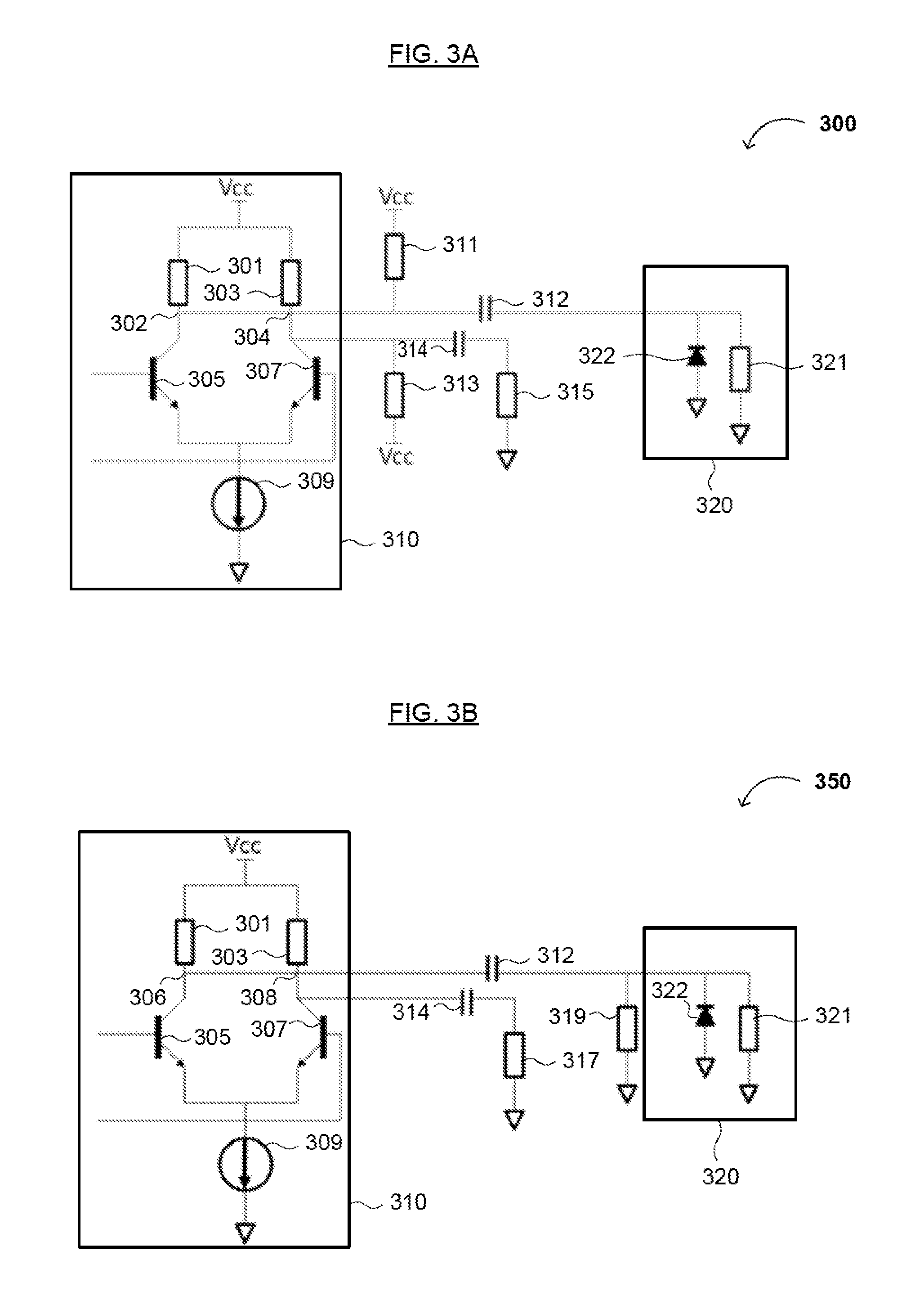
driver circuit is used to drive the EML laser to reduce power consumption. Typically, the DML laser driver consumes about half of the power of the EML laser driver. Additionally, in some embodiments, an impedance matching circuit is used to modulate an electro-absorption (EA) modulator of the EML laser to maximize efficiency when the output impedance of the DML laser driver circuit does not match the input impedance of the EML laser. The DML laser driver circuit that drives the EML laser is controlled via a microcontroller that may be configured to adjust a cross point, control an output voltage amplitude and / or a pre-emphasis function, and / or accurately drive the EML laser (optionally, with maximum efficiency).
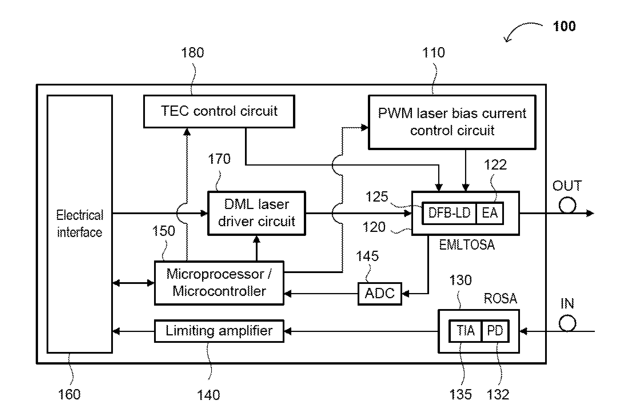
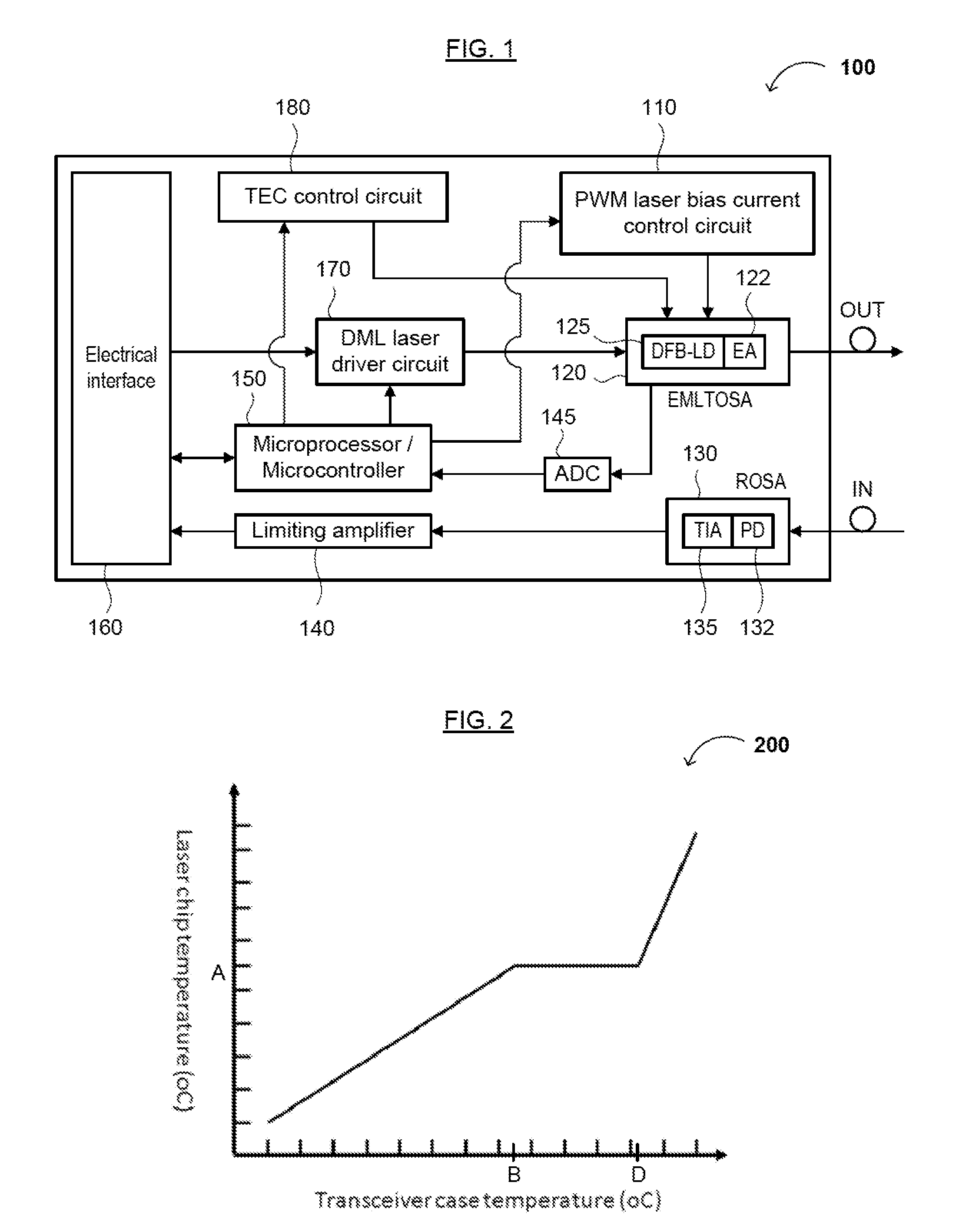
[0008]In another embodiment, and to further reduce power consumption, the present EML laser can be configured to apply a semi-cooling method and divide the working temperature of the EML laser into 2 or more ranges, where each temperature range or EML laser chip temperature profile (or group of settings) has a corresponding set or predetermined value or range of values based on ambient temperature or the transceiver module case temperature. Additionally, the present invention can include a micro-controller configured to (i) obtain a voltage of a thermal resistor in the EML laser via an analog-to-digital converter (ADC), (ii) detect an internal temperature of the EML laser, (iii) determine a corresponding operating temperature range for the EML laser, (iv) set a corresponding temperature value within the operating temperature range for the EML laser via a control circuit, and / or (v) limit the temperature of the EML laser within the operating temperature range via the (temperature) control circuit. The EML laser chip temperature settings or temperature profile consists of a constant temperature setting and / or a linear temperature relationship for a predetermined temperature range of the EML laser. In commercial applications, transceivers with EML lasers generally operate at a module case temperature in the range of −5° C. to 70° C. Thus, conventional transceivers' design requires heating at lower temperatures and cooling at higher temperatures, and conventional transceivers also always consume power since the EML laser chip temperature is set to a constant temperature regardless of the transceiver's operating temperature. For example, in such transceivers, a fixed temperature T is set for the laser within the operational temperature range of the transceiver, and the fixed temperature T is maintained by cooling the EML laser when the EML laser is at a higher operating temperature and heating the laser when it is at a lower operating temperature. The greater the temperature difference, the greater the cooling or heating required to reach the fixed temperature T, and the more power consumed in doing so.
[0009]In the present invention, the laser semi-cooling method has been utilized to adjust and / or tune the laser chip temperature setting range to minimize power consumption. For example, a first temperature (e.g., T1), a second temperature (e.g., T2), and a third temperature (T3) can be utilized, wherein T2 is the normal (standard operating) temperature, T1 is a lower temperature, and T3 is a higher temperature. When utilizing several temperatures, the laser may function at temperature T1 when the operating temperature decreases, and at temperature T3 when the operating temperature increases, thereby reducing temperature variations and differences, and reducing power consumption accordingly. That is, temperature ranges are set using corresponding target temperatures closer to the actual operating temperature, so as to reduce the amplitude of temperature adjustment (if necessary), thereby reducing power consumption. By utilizing temperatures T1, T2 and T3, different temperature profiles can be utilized, such as a linear curve or an exponential curve for the temperature fluctuations between temperatures T1 and T2, temperatures T2 and T3, etc.
[0012]In the present invention, a low power requirement DC / DC converter may be used to directly provide an accurate, continuous current supply to the EML laser. The DC / DC converter has high efficiency as a current source for laser bias current. Compared to existing technology, the present long reach transceiver has a low-power requirement and is able to reduce power consumption and increase transceiver efficiency (precision). These and other advantages of the present invention will become readily apparent from the detailed description of various embodiments below.

Problems solved by technology

Typically, the DML laser driver consumes about half of the power of the EML laser driver.
In commercial applications, transceivers with EML lasers generally operate at a module case temperature in the range of −5° C. to 70° C. Thus, conventional transceivers' design requires heating at lower temperatures and cooling at higher temperatures, and conventional transceivers also always consume power since the EML laser chip temperature is set to a constant temperature regardless of the transceiver's operating temperature.

Method used


Image

  • Low Power Consumption, Long Range, Pluggable Transceiver, Circuits and Devices Therefor, and Method(s) of Using the Same
  • Low Power Consumption, Long Range, Pluggable Transceiver, Circuits and Devices Therefor, and Method(s) of Using the Same
  • Low Power Consumption, Long Range, Pluggable Transceiver, Circuits and Devices Therefor, and Method(s) of Using the Same

Examples


Embodiment Construction

[0020]Reference will now be made in detail to various embodiments of the invention, examples of which are illustrated in the accompanying drawing(s). In order to achieve the objectives, technical solutions and advantages of the present invention more clearly, further details of the invention are described below with regard to the Figure(s). While the invention will be described in conjunction with the following embodiments, it will be understood that the descriptions are not intended to limit the invention to these embodiments. On the contrary, the invention is intended to cover alternatives, modifications and equivalents that may be included within the spirit and scope of the invention as defined by the appended claims. Furthermore, in the following detailed description, numerous specific details are set forth in order to provide a thorough understanding of the present invention. However, it will be readily apparent to one skilled in the art that the present invention may be practi...


PUM


Abstract

The present disclosure relates to an optical transceiver for use in optical fiber communications and / or telecommunications systems and, more specifically, a low power consumption, long range pluggable transceiver. The transceiver generally comprises a photodiode with a transimpedance amplifier (PIN-TIA); an electro-absorption modulated laser (EML); an optical detector; and a directly modulated laser (DML) driving module connected between the PIN-TIA and EML laser configured to drive the EML laser. A low power-consumption DML driving module is utilized to drive the EML laser, so as to further reduce power consumption. An impedance matching circuit can be applied to modulate an electro-absorption (EA) modulator of the EML laser with maximum efficiency.

Description

FIELD OF THE INVENTION[0001]The present invention generally relates to the field of optoelectronic conversion devices (e.g., optical transceivers) in fiber optic communications and telecommunications. More specifically, embodiments of the present invention pertain to a long range, low power, small form-factor pluggable (SFP+) transceiver, circuits and devices therefor, and method(s) of using the same.DISCUSSION OF THE BACKGROUND[0002]As a core component of optical (e.g., fiber-optic) communications networks, optical transceivers have provided optical data transmission systems with low cost, large capacity, and low power consumption. Such transceivers make fiber-optic networks more complete, smaller, and can increase access to the transceiver interface board. Such transceivers comprise optoelectronic component(s), functional circuitry, a laser and a photodiode-transimpedance amplifier (PIN-TIA), in which the optoelectronic component(s) include both transmitter and receiver circuitry....

Claims


Application Information

Patent Timeline
Patent Type & Authority Applications(United States)
IPC IPC(8): H04B10/00H01J7/24H04B10/04
CPCH04B10/40
Inventor HU, ZHAOYANGZENG, LINGQIONGLILJEBERG, THOMAS
Owner SOURCE PHOTONICS
Why Eureka
Try Eureka