Method and arrangement for robust interferometry

a robust interferometer and method technology, applied in the direction of interferometers, measurement devices, instruments, etc., can solve the problems of inability to achieve long-term stability of interferometers, inability to measure long-term stability, and undetectable lateral offset of object wavefronts, etc., to achieve numerically determined comparatively accurately, increase the depth measurement range, and increase the coherence length

Active Publication Date: 2012-12-06
UNIV STUTTGART
View PDF14 Cites 42 Cited by
  • Summary
  • Abstract
  • Description
  • Claims
  • Application Information

AI Technical Summary

Benefits of technology

[0124]In the method for robust interferometry, preferably in the object beam path a chromatic depth splitting of foci is carried out in a predetermined manner with spectrally refractive-power-variable means in the object beam path. The depth measurement range can thus be increased.
[0125]In the method for robust interferometry, preferably radiation from the object is confocally discriminated after the second passage of the spectrally refractive-power-variable means. Afterward, said radiation from the object is superimposed with radiation from the reference beam path in order to form at least one spatial interferogram and the intensity distribution of the spatial interferogram is subjected to a Fourier transformation according to the method of Fourier transformation spectroscopy in order to obtain the spectrum also of confocally discriminated radiation from the object after chromatic depth splitting, in order to determine from this spectrum the distance, the depth, the profile, the form, undulation and/or the roughness or the optical path length of an object. For this purpose, a centroid evaluation can be carried out. In this case, substantially only the wavelength components which were sharply focused on the object, that is to say formed foci there, and were accordingly able to pass through a confocal diaphragm lead to appreciable components in the spectrum. The spectrally broadband intensity component from the reference beam path is not manifested in a modulation in the interferogram, nor is it therefore manifested in the spectrum calculated by Fourier transformation, since the broadband intensity components from the object beam path have already been lost on account of the depth splitting of foci with subsequent confocal discrimination and, consequently, cannot contribute to the formation of interference. Only the component of light from the reference beam path is spectrally comparatively broadband here, but owing to the lack of spectrally broadband object light components it cannot lead to a modulation in the interferogram....

Problems solved by technology

However, said downstream inclination device described in DE 10 2006 015 387 A1 is complex—including in terms of alignment—and generally very susceptible to undesirable misalignments and, consequently, the interferometer generally also does not exhibit long-term stability.
Thus, the signal waveform of a short-coherent spatial interferogram can also change in an unknown manner, which can constitute a considerable disadvantage for the evaluation.
A targeted change in the angular magnitude by means of an inclination device, for example in order to change the spatial frequency for the centroid wavelength in the spatial interferogram in a predetermined manner, can lead to an undesired lateral offset of object wavefront and reference wavefront during detection, which can be compensated for only in a complex manner or cannot be compensated for at all by an alignment in some cases.
Thus, the possibility of changing the spatial frequency for the centroid wavelength in the spatial interferogram in a simple manner is greatly restricted in the case of this arrangement.
Furthermore, in the case of a sub-optimal alignment of the very complex interferometer, an only partial lateral overlap of object wavefront and reference wavefront can occur permanently, which can constitute a source of measurement errors or can con...

Method used


Image

  • Method and arrangement for robust interferometry
  • Method and arrangement for robust interferometry
  • Method and arrangement for robust interferometry

Examples


Embodiment Construction

[0215]The term light is always used herein as a synonym for electromagnetic radiation from the terahertz through infrared to deep UV spectrum.

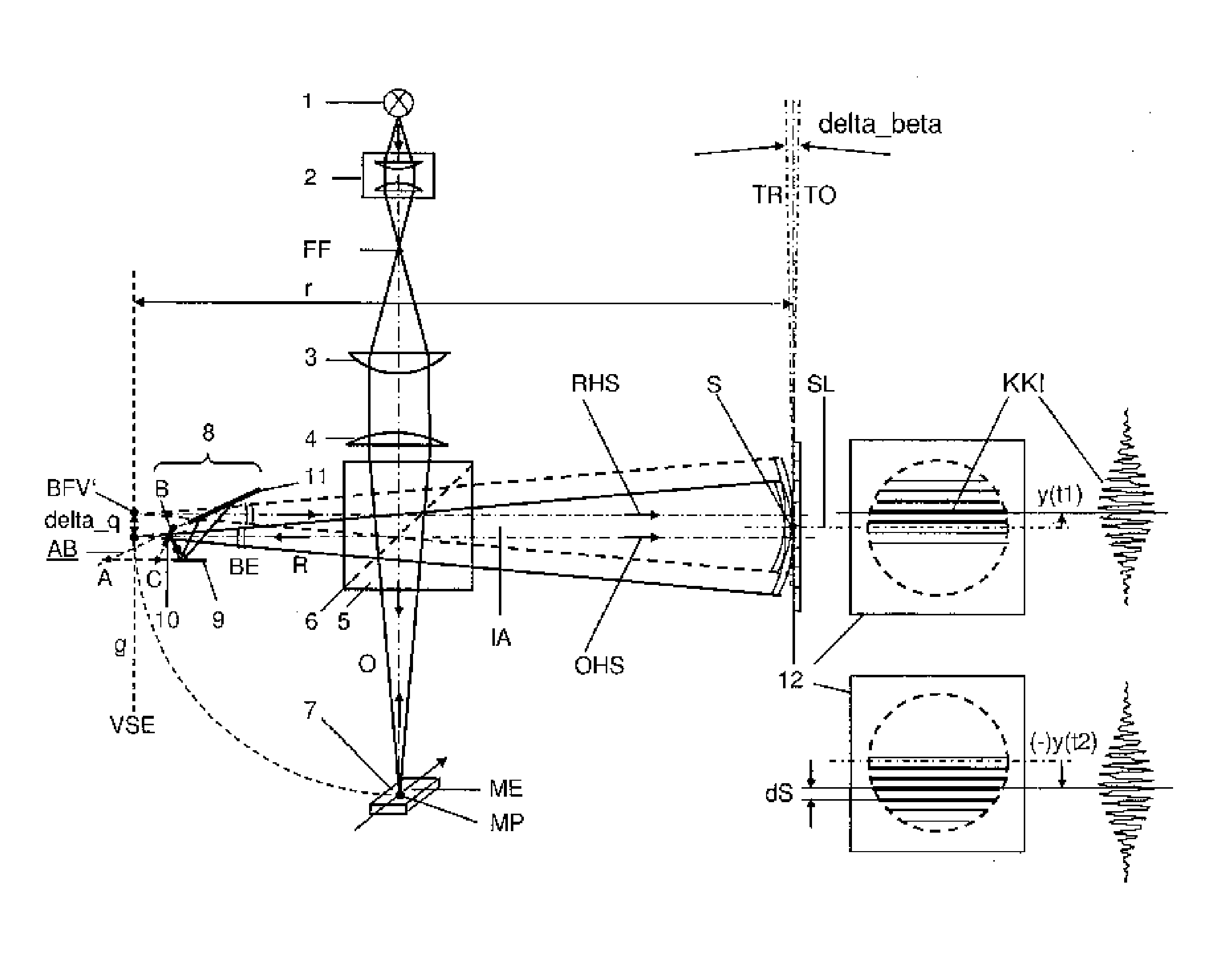
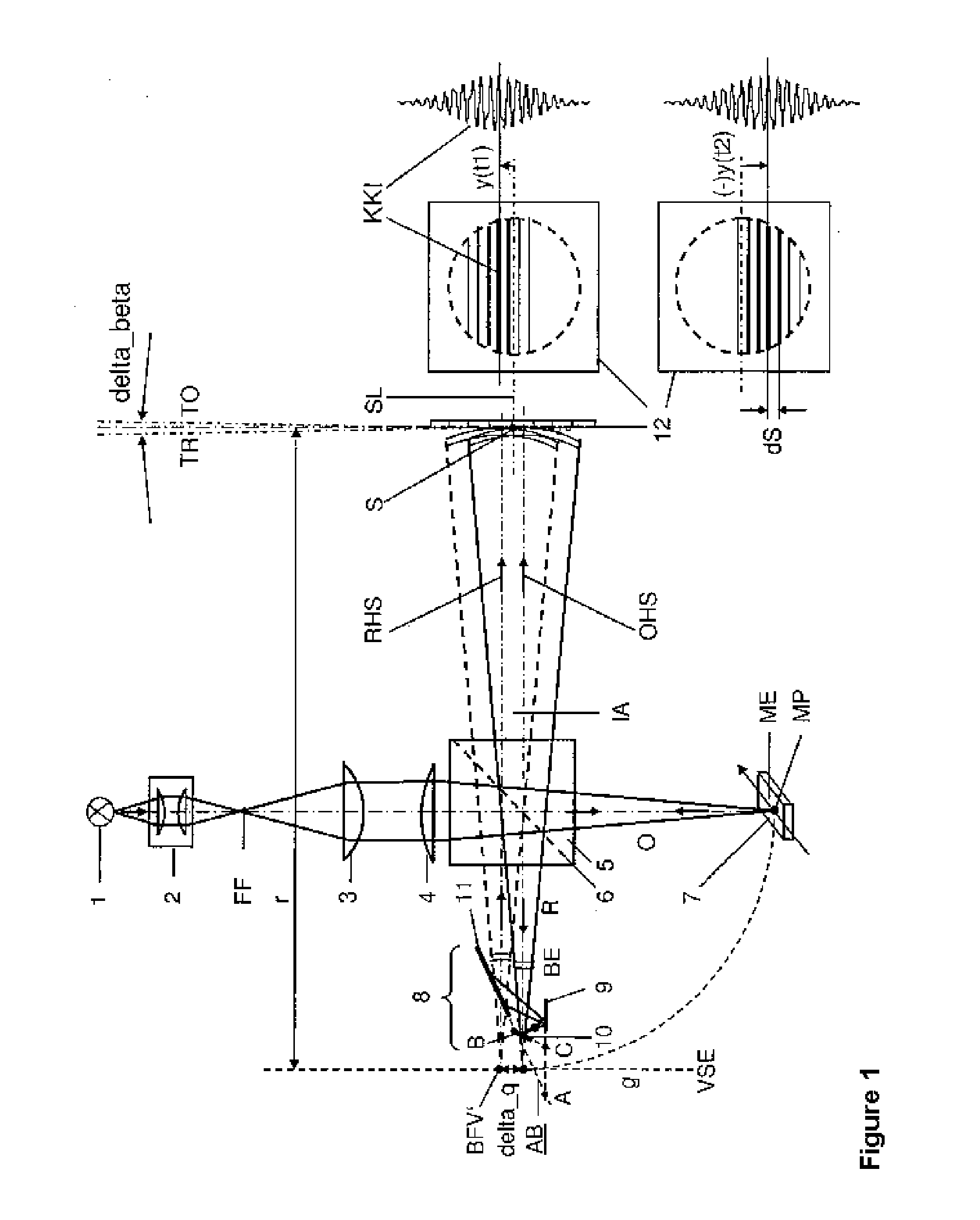
[0216]FIG. 1 shows a sensor on the basis of a Michelson interferometer. The light from a spectrally comparatively broadband light source 1 in the near infrared range is brought to a small focal spot FF by means of a beam shaping optical system 2, it also being possible to arrange a pinhole here, is collimated by a lens 3 and is focused again by a comparatively small-aperture focusing lens 4 having a numerical aperture of 0.05 and subsequently passes into a Michelson-type interferometer comprising a beam splitter 5 and a beam splitter surface 6, where the light is split into a reference beam R and an object beam O. The object light beam O passing rectilinearly through the beam splitter 5 impinges on the reflective object surface of the object 7 in a manner focused at the measurement point MP, said surface being situated here almost in the measu...


PUM


Abstract

An arrangement and a method are provided for robust interferometry for detecting distance, depth, profile, form, undulation, flatness deviation and/or roughness or the optical path length in or on technical or biological objects, including in layered form, or else for optical coherence tomography (OCT), with a source of electromagnetic radiation and with an interferometer, in particular also in the form of an interference microscope, having an object beam path and having a reference beam path, in which an end reflector is arranged, and a line-scan detector for detecting electromagnetic radiation in the form of at least one spatial interferogram.

Description

BACKGROUND OF THE INVENTION[0001]1. Field of the Invention[0002]The published patent application DE 10 2006 015 387 A1 by M. Hering et al. discloses an interferometric measuring device on the basis of white light interferometry, also known as short-coherence interferometry, wherein the wavefronts of the reflected object ray and those of the reflected reference ray are inclined with respect to one another by a specific angular magnitude by means of an inclination device, such that a spatial interferogram can arise as a single-shot data set. By way of example, said angular magnitude is realized here in a greatly modified Linnik interferometer arrangement, which also has features of a Mach-Zender interferometer, by means of a tilting mirror through which light passes only once on the path to detection. In this case, the tilting mirror disposed downstream of the Linnik arrangement, is situated in an infinite beam path for the object light and is still part of the interferometer.[0003]2....

Claims


Application Information

Patent Timeline
IPC IPC(8): G01B11/02G01B9/02
CPCG01B9/0209G01B2290/15G01B9/02061G01B9/02032
Inventor KOERNER, KLAUSBERGER, REINHARDOSTEN, WOLFGANG
Owner UNIV STUTTGART
Why Eureka
Try Eureka