
Light-emitting device

a light-emitting device and light-emitting technology, which is applied in the direction of luminescent compositions, energy-efficient lighting, sustainable buildings, etc., can solve the problems of reducing the light-emitting device's light-emitting efficiency and not ideal for warm emission, and achieve efficient white light emission and high ra and r9.

Active Publication Date: 2012-12-20
NAT INST FOR MATERIALS SCI
View PDF4 Cites 6 Cited by
  • Summary
  • Abstract
  • Description
  • Claims
  • Application Information

AI Technical Summary

Benefits of technology

The present invention is a light-emitting device that emits white light in the incandescent bulb color range with high efficiency. The device uses a combination of a green phosphor and an orange phosphor that exhibits a broader emission spectrum with a narrower FWHM (full width at half maximum) than the yellow thru / or red phosphor. By using an orange phosphor with a broader FWHM and a narrower absorptance peak wavelength, the device exhibits good color rendering and high efficiency. The technical effect of the invention is to provide a light-emitting device that emits white light in the incandescent bulb color range with high efficiency and good color rendering.

Problems solved by technology

The configuration is short on emission of red light due to the light-emitting properties of the YAG phosphor, and thus is not ideal for emission of warm white light that resembles the incandescent bulb color, which warm white light is in the need for home lighting fixtures and other applications.
In this manner, a large proportion of light emitted by one phosphor is absorbed by another phosphor (mutual light absorption of phosphors), thereby greatly reducing light emission efficiency of the light-emitting device.

Method used


Image

  • Light-emitting device
  • Light-emitting device
  • Light-emitting device

Examples


production example 1-1

Preparation 1 of Orange Phosphor

[0149]A phosphor was synthesized by having a crystal composed of 0.3CaAlSiN3.0.7LiSi2N3 serve as a crystal of a host material, and activating this with Ce.

[0150]More specifically, to obtain a compound having a theoretical composition formula of Ce0.0033Li0.1157Ca0.0496Al0.0496Si0.28O00.0050N0.4959, starting powder was weighed so that a whole amount was 2 g with a composition ratio of Si3N4:67.3% by weight, AlN: 10.4% by weight, Li3N: 6.9% by weight, Ca3N2: 12.5% by weight, and CeO2: 2.92% by weight, and was mixed for 10 minutes with an agate pestle and mortar. At this time, the ratio of Ce in the starting powder was 2.4% by weight. Thereafter, an obtained mixture was gravity-dropped and filled into a crucible made of boron nitride (volume filled by 38%).

[0151]Note that each of the processes of the weighing and mixing of the powder were performed inside a glove box capable of maintaining a nitrogen atmosphere including moisture equal to or less than 1 ...

production example 1-2

Preparation 2 of Orange Phosphor

[0161]A phosphor was synthesized by having a crystal composed of 0.3CaAlSiN3.0.7LiSi2N3 serve as a crystal of a host material, and activating this with Ce.

[0162]More specifically, to obtain a compound having a theoretical composition formula of Ce0.066Li0.1148Ca0.0492Al0.0492Si0.2787O0.0098N0.4918, starting powder was weighed so that a whole amount was 2 g with a composition ratio of Si3N4:65.4% by weight, AlN: 10.1% by weight, Li3N, 6.7% by weight, Ca3N2: 12.2% by weight, and CeO2: 5.66% by weight, and the powder was mixed for 10 minutes with an agate pestle and mortar. At this time, a charge weight ratio of Ce was 4.6% by weight. Thereafter, an obtained mixture was gravity-dropped and filled into a crucible made of boron nitride (volume filled by 38%).

[0163]Note that each of the processes of the weighing and mixing of the powder were performed inside a glove box capable of maintaining a nitrogen atmosphere including moisture equal to or less than 1 ...

production example 2-1

Preparation 1 of Eu-Activated β-Sialon Phosphor

[0179]In order to obtain an Eu-activated β-sialon phosphor in which Eu was 0.09 at. %-activated in a substance having the composition formula represented by Si6-z.Alz.Oz.N8-z′ where z′ was 0.23, powders were weighed so as to have a composition of 95.82% by weight of α-silicon nitride powder, 3.37% by weight of aluminum nitride powder and 0.81% by weight of europium oxide powder. The powders were mixed for 10 or more minutes with use of a mortar and pestle made of sintered silicon nitride, to obtain a powder aggregate. The powder aggregate was gravity-dropped into a crucible made of boron nitride whose diameter was 20 mm and height was 20 mm.

[0180]Subsequently, the crucible was set to a gas pressure sintering furnace of a graphite resistance heating system. The baking atmosphere was vacuumed with a diffusion pump and was heated from room temperature to 800° C. at a rate of 500° C. per hour. Thereafter at 800° C., nitrogen having a purity...


PUM


Abstract

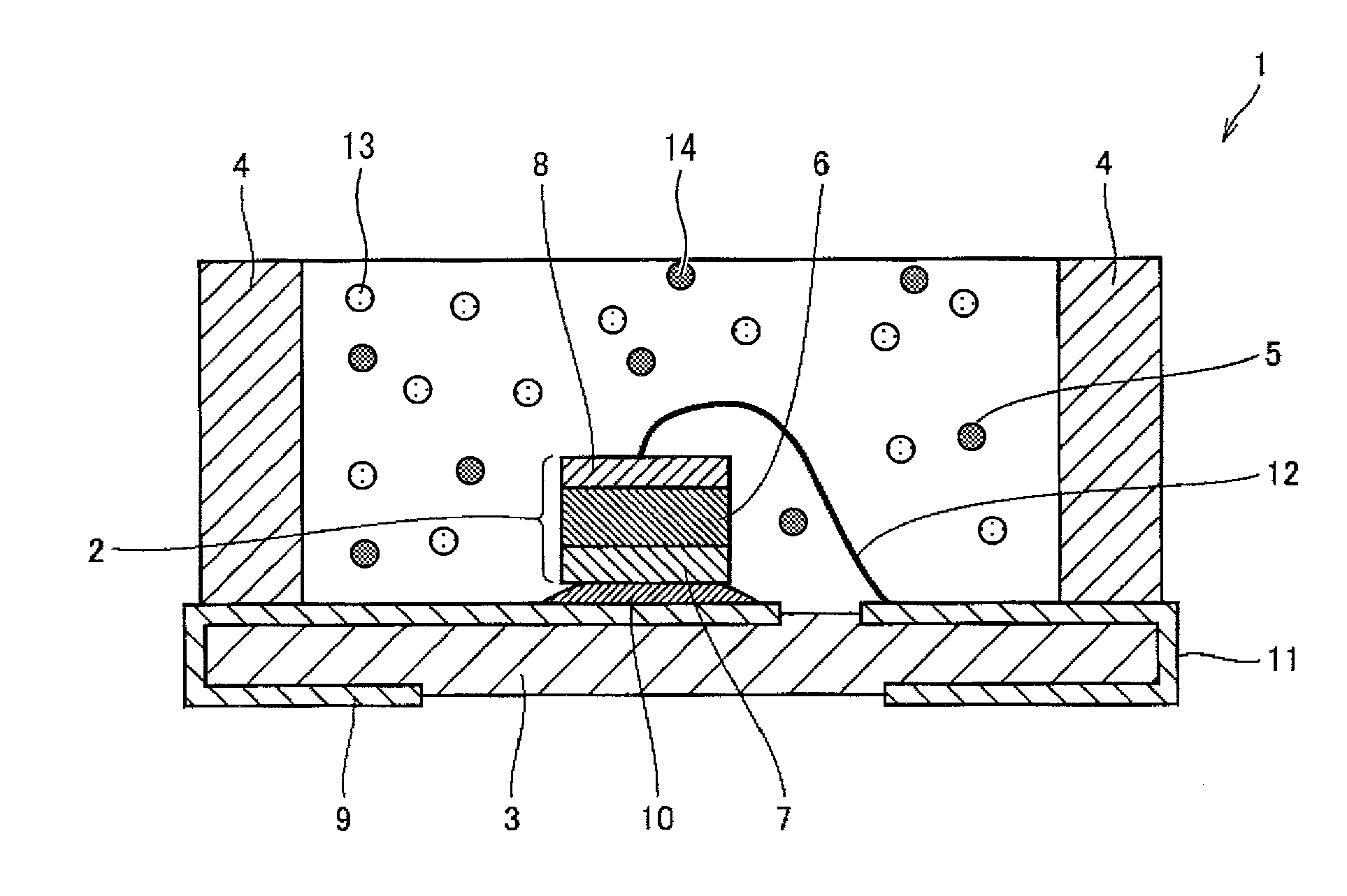
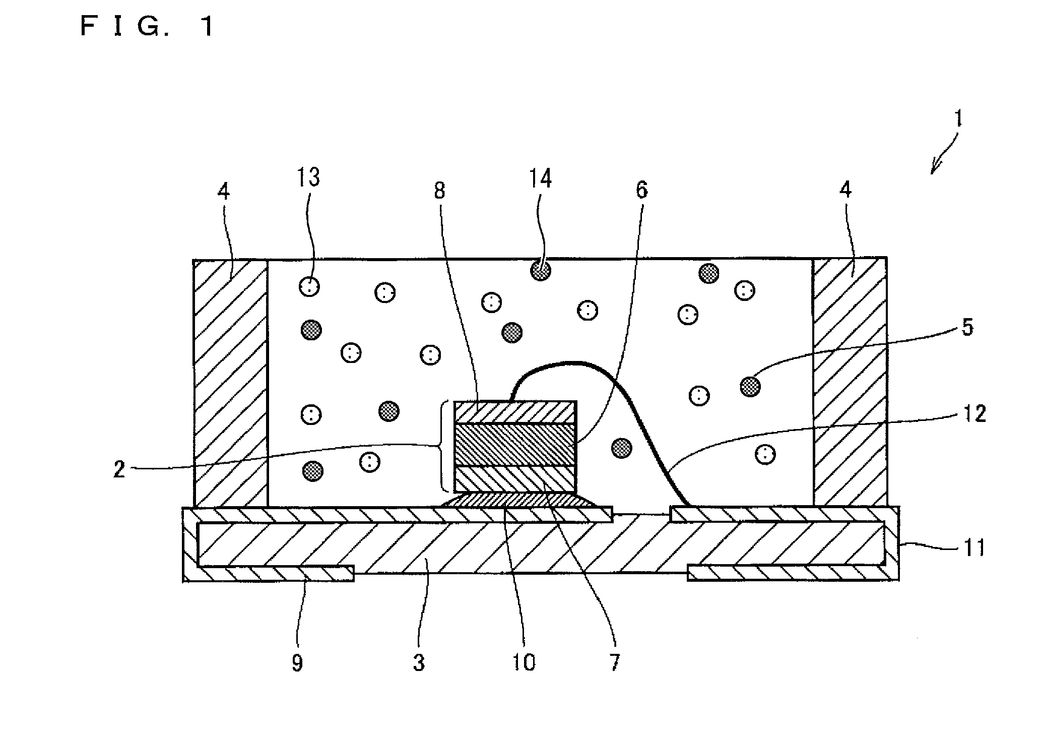
Disclosed is a light-emitting device that exhibits good color rendering and highly efficiently emits white light in an incandescent bulb color range. The semiconductor light-emitting device (1) of the present invention includes: a semiconductor light-emitting element (2) that emits blue light; a green phosphor (14) that absorbs the blue light and emits green light; and an orange phosphor (13) that absorbs the blue light and emits orange light. The orange phosphor (13) produces an emission spectrum having a peak at a wavelength of equal to or greater than 590 nm but equal to or less than 630 nm and having a full width at half maximum of 130 nm or greater at the peak, the full width at half maximum of the emission spectrum of the orange phosphor (13) being broader than a full width at half maximum of an emission spectrum of the green phosphor (14). The orange phosphor (13) exhibits an absorptance having a peak wavelength of 420 nm or greater. ABS(530) and ABS(MAX) satisfy a relation, ABS(530) / ABS(MAX)<0.60, where ABS(MAX) is an absorptance of the orange phosphor (13) at the peak wavelength thereof, and ABS(530) is an absorptance of the orange phosphor (13) at a wavelength of 530 nm.

Description

REFERENCE TO RELATED APPLICATIONS[0001]This application is a national stage application under 35 USC 371 of International Application No. PCT / JP2011 / 051600, filed Jan. 27, 2011, which claims priority from Japanese Patent Application No. 2010-043107 filed Feb. 26, 2010, the entire contents of which are incorporated herein by reference.FIELD OF THE INVENTION[0002]The present invention relates to a light-emitting device including a phosphor.BACKGROUND OF THE INVENTION[0003]Light-emitting diodes (LEDs) and like semiconductor light-emitting elements have advantages of being compact, low power consuming, and being capable of stable, high-luminance light emission. Lighting fixtures that use light-emitting devices provided with white-light-emitting LEDs have progressively replaced incandescent lamps and other lighting fixtures. Examples of the white-light-emitting LED include combinations of blue LEDs and YAG phosphor (composition being (Y,Gd)3(Al,Ga)5O12).[0004]The light-emitting device th...

Claims


Application Information

Patent Timeline
Patent Type & Authority Applications(United States)
IPC IPC(8): H01L33/50
CPCC09K11/64H01L33/504Y02B20/181H05B33/14C09K11/7734C09K11/7792C09K11/0883H01L2924/181H01L2224/48091H01L2224/73265Y02B20/00C09K11/77347C09K11/77348H01L2924/00012H01L2924/00014
Inventor YOSHIMURA, KENICHIFUKUNAGA, HIROSHITAKAHASHI, KOHSEIHIROSAKI, NAOTO
Owner NAT INST FOR MATERIALS SCI
Learn More