Eureka AIR delivers breakthrough ideas for toughest innovation challenges, trusted by R&D personnel around the world.

Direct extrusion method for the fabrication of photonic band gap (PBG) fibers and fiber preforms

a technology of photonic band gap and extrusion method, which is applied in the direction of manufacturing tools, instruments, cladded optical fibers, etc., can solve the problems of inability to meet the requirements of the production process

Active Publication Date: 2012-12-20
NAVY U S A AS REPRESENTED BY THE SEC OF THE THE
View PDF7 Cites 13 Cited by
  • Summary
  • Abstract
  • Description
  • Claims
  • Application Information

AI Technical Summary

Benefits of technology

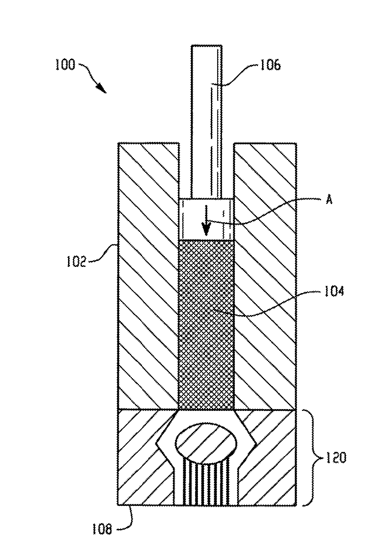
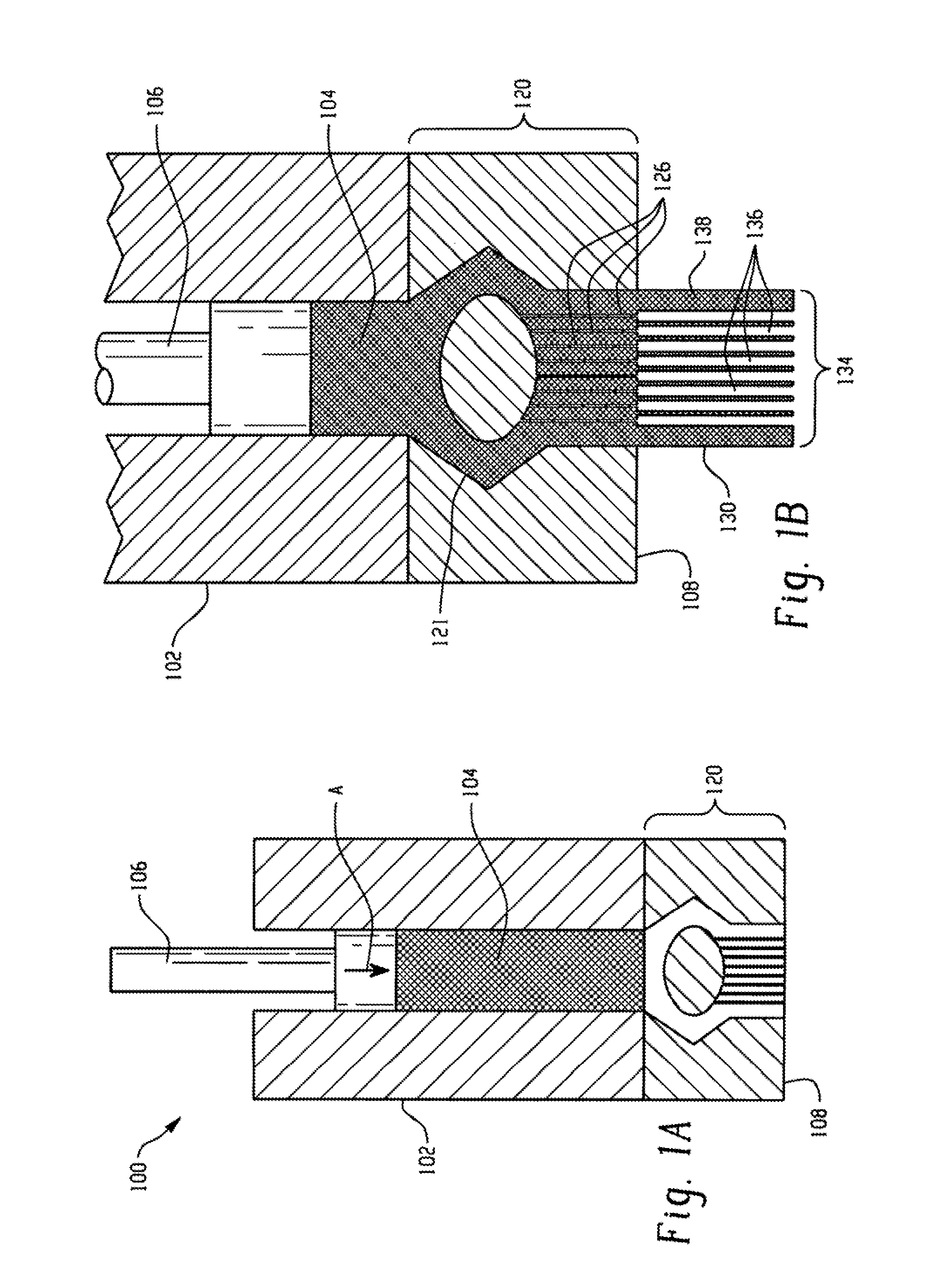
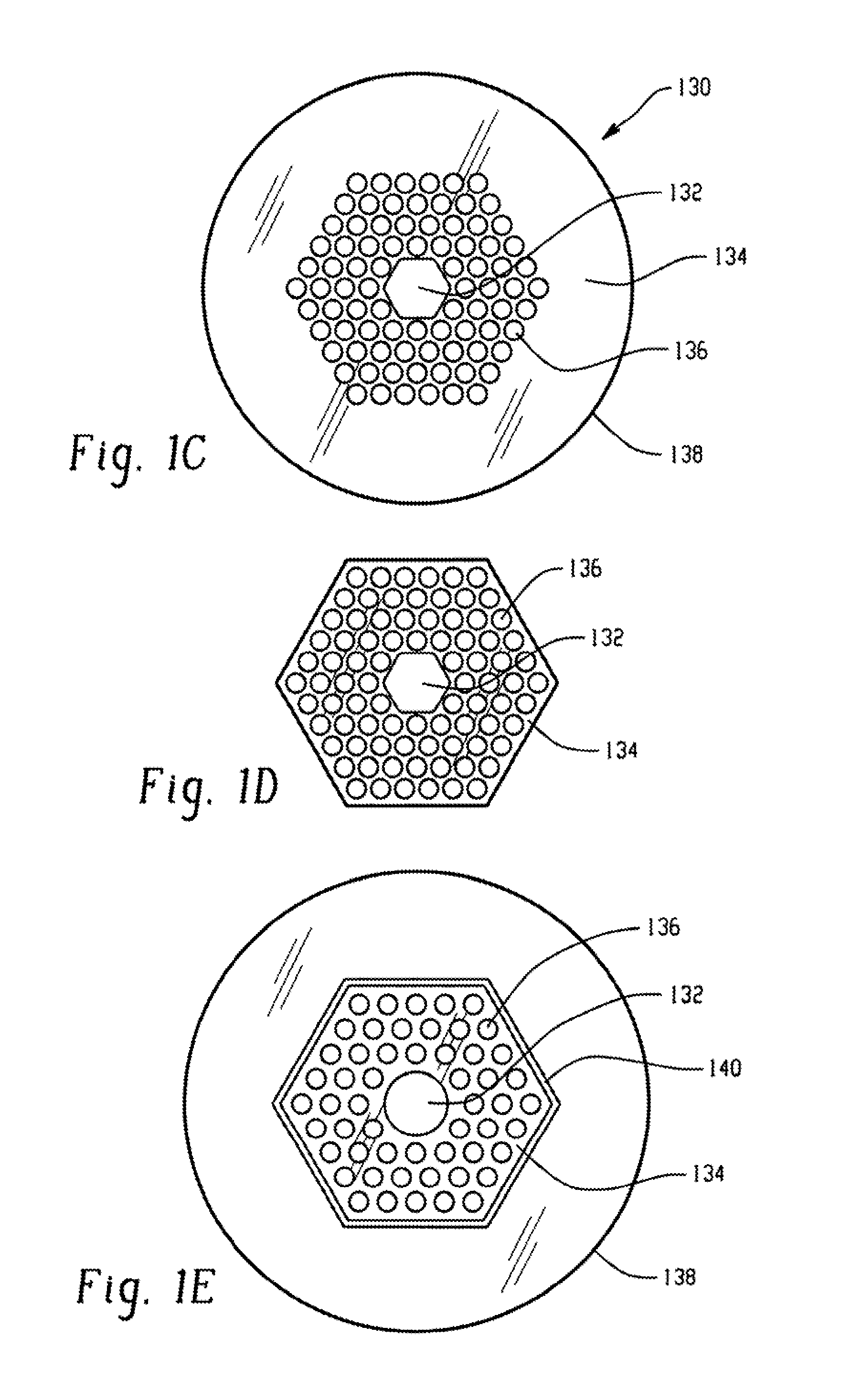
[0015]The present invention provides a method and an apparatus for making a HC-PBG fiber preform by a direct extrusion process, the preform suitable for fabricating a substantially void-free microstructured optical fiber. In the method of the present invention, a preform for the optical fiber is prepared from specialty glass and comprises a structured inner region, or a structured inner region surrounded by a jacket region, wherein either the structured inner region, or the structured inner region and the outer jacket region, are formed by direct extrusion of the specialty glass through a structured die. The thus-prepared preform is then placed into a fiber draw tower to render void-free HC-PBG fibers. Thus, the final microstructured fiber can be prepared in one step, without the need for employing a consolidation step to remove interstitial voids, as used in other methods, given that no such voids are present. Interstitial voids, as noted above, are the result of using a preform fabricated from stacked microtubes. As no stacking process or microtubes are used in the current method, the creation of unintended voids is eliminated.
[0016]The preforms according to the present invention can include one or more components fabricated from specialty non-silica glass, such as chalcogenide and chalcohalide glasses and other oxide glasses including specialty silicates, germanates, phosphates, borates, gallates, tellurites, antimonates and their mixtures. Such specialty glasses are characterized by a much lower softening temperature than silica glasses, making them better suited for certain fabrication processes, specifically direct extrusion processing, wherein the entire structured region of the preform is formed in a single extrusion step. The method provided herein has an advantage in this regard over other processes wherein silica glasses, that require much higher processing temperatures, are used.

Problems solved by technology

However, due to the nature of the materials used, such conventional fibers still exhibit some absorption and scattering of the light traveling through them and can therefore suffer some loss as the signal travels through the fiber.
However, because the microtubes and / or microcanes comprising the cladding do not always fit together perfectly, the assembly process inevitably introduces gaps, or voids, at the interfaces between the microtubes / microcanes or between the cladding area and the outer jacket.
Additionally, conventional processes rely on stacking the microtubes or microcanes, by hand or otherwise, which may result in errors in the periodicity of the fiber produced, as well as additional gaps or voids.
The presence of both the interfacial and interstitial voids is undesirable.
The interfacial voids run the entire length of the preform and have a size similar to that of the intended holes in the structured region and so can make fiberization difficult.
Furthermore, the accuracy of the periodicity and position of the intended holes is critical to attaining band gap guidance in the fiber, and is adversely affected by the presence of such “stray” holes in the fiber caused by incorrect tube positioning and tube slippage during fiberization, which can destroy the ability of the fiber to perform properly.
As such, interstitial voids are common deficiencies of the tube stacking preform method.
However, this two-step process still leaves an undesirable number of interstitial voids in the finished fiber.
However, this may cause soot to accumulate on the preform that can interfere with optical performance of the HC-PBG fiber.
Other processes have been attempted, but no process has achieved the desired result of rendering a HC-PBG fiber devoid of interstitial spaces that degrade fiber performance.

Method used


Image

  • Direct extrusion method for the fabrication of photonic band gap (PBG) fibers and fiber preforms
  • Direct extrusion method for the fabrication of photonic band gap (PBG) fibers and fiber preforms
  • Direct extrusion method for the fabrication of photonic band gap (PBG) fibers and fiber preforms

Examples


Embodiment Construction

[0026]The aspects and features of the present invention summarized above can be embodied in several different forms. The following description shows, by way of illustration, various combinations and configurations in which aspects and features of the invention can be put into practice. It is understood that the aspects, features, and / or embodiments described herein are merely examples, and that one skilled in the art may utilize other aspects, features, and / or embodiments or may make structural and functional modifications without departing from the scope of the present disclosure.

[0027]In describing optical fibers, the term “microstructured” is typically used to describe a structure with features on the micro scale (between approximately 1 μm and 1000 μm) and the term “structured” is typically used to describe features of any scale, including features smaller than, larger than, or the same size as “microstructured” features. In the present disclosure, the term “microstructured” is ...


PUM

PropertyMeasurementUnit
infra-red wavelengthsaaaaaaaaaa
wavelengthaaaaaaaaaa
viscosityaaaaaaaaaa

Abstract

A method and apparatus for making a substantially void-free preform for a microstructured optical fiber using a one-step process is provided. A preform is prepared from specialty glasses using a direct extrusion method. A die for use with the direct extrusion method is also provided, and a method for drawing the preform into a HC-PBG fiber for use in transmitting infra-red wavelength light is also provided. The preform comprises an outer jacket made of solid glass, a cladding having a plurality of air holes arranged in a desired pattern within the jacket, and a core which is hollow.

Description

TECHNICAL FIELD[0001]The present invention relates to a novel method to make preforms from specialty glass for microstructured photonic band gap (PBG) fibers, to the structured preforms fabricated by the method, and to the microstructured PBG fibers drawn from the preforms.BACKGROUND[0002]Optical fibers have found increasing uses in industrial, scientific, and military applications. Conventional optical fibers guide light passing through them using the principles of total internal reflection. Total internal reflection (TIR) occurs when light travels through a material having a high index of refraction n and strikes an interface between that material and a material having a lower value of n. If the angle of incidence of the light on the interface is greater than some angle, known as the “critical angle,”θc, the light cannot pass through the interface into the lower-refractive material but instead is reflected back into the higher-refractive material. Thus, for optical glass fibers, t...

Claims


Application Information

Patent Timeline
Patent Type & Authority Applications(United States)
IPC IPC(8): G02B6/032C03B37/022G02B6/02
CPCC03B37/0122C03B37/01274C03B2201/06C03B2201/60C03B2201/62C03B2201/70C03B2201/78C03B2201/86C03B2201/88C03B2203/14C03B2203/16C03B2203/42G02B6/02328G02B6/02347C03C13/04C03C13/043C03C3/321C03C4/10
Inventor GIBSON, DANIEL J.SANGHERA, JASBINDER S.KUNG, FREDERIC H.PUREZA, PABLO C.MIKLOS, ROBERT E.VILLALOBOS, GUILLERMO R.SHAW, LESLIE BRANDONAGGARWAL, ISHWAR D.
Owner NAVY U S A AS REPRESENTED BY THE SEC OF THE THE
Why Eureka
Eureka Blog
Learn More