Coated film drying furnace

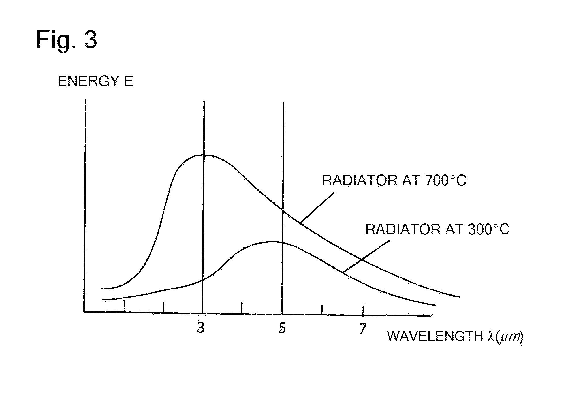
a drying furnace and film technology, applied in the direction of drying machines with progressive movements, furnace heating elements, furnaces, etc., can solve the problems of large-scale continuous furnaces that cannot the amount of radiant energy in the near infrared range of 3.5 m or less as aimed is very small, and the furnace can not meet the needs of large-scale continuous furnaces. , to achieve the effect of suppressing the atmospheric temperature, reducing energy

Active Publication Date: 2012-12-27
NGK INSULATORS LTD
View PDF23 Cites 12 Cited by
  • Summary
  • Abstract
  • Description
  • Claims
  • Application Information

AI Technical Summary

Benefits of technology

[0018]The coated film drying furnace of the present invention has the infrared heater in which the outer circumference of the filament is covered concentrically by the plurality of tubes that functions as the low pass filter, and has the structure in which the fluid flow passage is formed between the plurality of tubes at inside the furnace body. This infrared heater can radiate the infrared rays, which adjusts the peak wavelength of short wavelength of 3.5 μm or less by making the filament a high temperature of 700° C. or more and 1200° C. or less, and is effective for dryness of a coated film. Thereby, the infrared heater enables sufficient dryness also in a continuous furnace like a roll-to-roll type. Further, since only the wavelength of 3.5 μm or less that contributes in cutting the intermolecular hydrogen bonds is selected, the temperature rise inside the furnace due to a long wavelength greater than 3.5 μm does not occur, and effective drying of the coated film b

Problems solved by technology

However, under such a condition, an amount of the radiant energy of the near infrared range of 3.5 μm or less as aimed is very small.
Further, the temperature may go beyond an ignition temperature of the evaporated organic solvent, and an explosion may occur.
However, these are all heaters for heating the fluid flowing in a flow passage surrounding the heater and are not for heating a work inside a furnace.
However, what is disclosed therein is a batch-type vapor phase epitaxy device, and is not a furnace for continuously drying a coated film having an

Method used


Image

  • Coated film drying furnace
  • Coated film drying furnace
  • Coated film drying furnace

Examples


examples

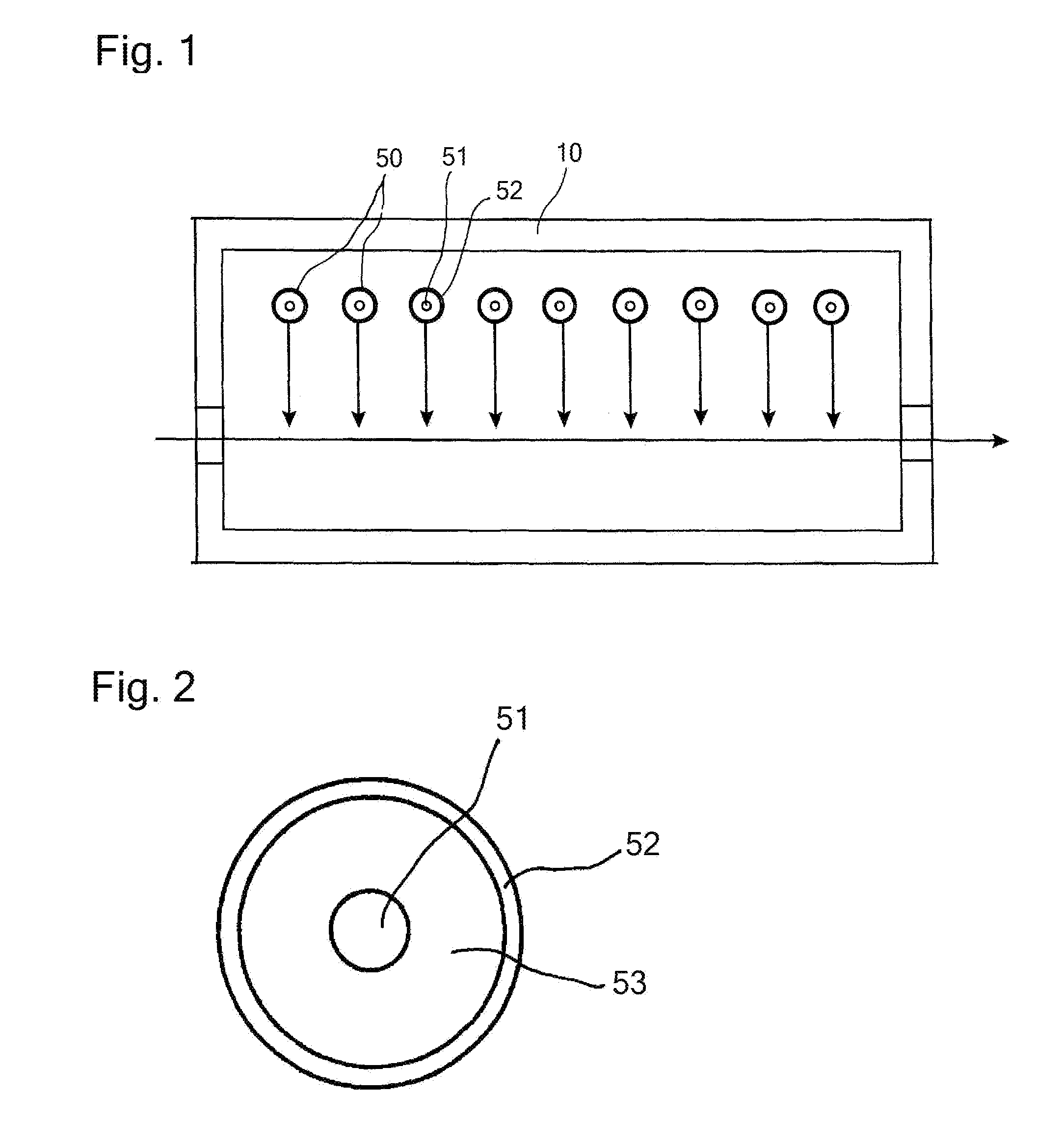
[0057]A furnace body with a length of 4 m was divided into two zones of front and back with 2 m each, 19 infrared heaters having the cross sectional structure shown in FIG. 2 were arranged on a furnace ceiling section at a 0.1 m pitch in the 2 m portion on the front side. A height of a furnace chamber was 0.3 m, and a height at which the infrared heaters were provided was 0.25 m. Further, a material of an outer circumference tube of each infrared heater was a quartz glass, with a diameter of 20 mm. A filament temperature of the infrared heaters was set at 850° C., and air was flown on an outer circumference thereof to maintain an outer surface temperature of the infrared heaters at 187° C. Note that the injected air was at 20° C. when starting to flow, but was at 129° C. when coming out from the infrared heaters. Spectrums of infrared rays radiated from the infrared heaters were measured, and near infrared rays with a peak wavelength of 3.2 μm were being radiated. Further, a tempera...


PUM


Abstract

A coated film drying furnace for drying a coated film inside a furnace body by conveying the coated film therein, the coated film having an absorption spectrum for electromagnetic waves of 3.5 μm or less and having hydrogen bonds, such as an electrode coated film for lithium ion battery. Infrared heaters provided inside a furnace body have outer circumferences of filaments concentrically covered by tubes that function as a low pass filter, and have a structure in which a fluid flow passage is formed at 16 between the plurality of tubes. Due to this, a temperature rise in the furnace is controlled so as to prevent explosion of an organic solvent vapor, and the coated film is efficiently heated and dried by intensively radiating near infrared rays of 3.5 μm or less that have superior ability to cut off the intermolecular hydrogen bonds onto a work.

Description

TECHNICAL FIELD[0001]The present invention relates to a coated film drying furnace used for a continuous drying of a coated film such as an electrode coated film for lithium ion battery and an electrode coated film for photovoltaic power generation.BACKGROUND ART[0002]In a process for manufacturing an electrode coated film for lithium ion battery, an electrode coated film for photovoltaic power generation, and the like, there has been a drying method suitable for heat-drying workpieces with a coated film formed on a sheet surface thereof. The drying method is performed such that a plurality of infrared heaters 50 arranged in a furnace body 10 undergoes hot-air heating or infrared heating while the workpieces are moved inside of the furnace as shown in FIG. 1. As the infrared heater 50 used in such a furnace, a heater having a protection tube 52 around a filament 51 at a center as shown in FIG. 2 has been widely used (Patent Document 1). The reference number 53 refers to a supporting...

Claims


Application Information

Patent Timeline
IPC IPC(8): F27D11/12F26B23/04F26B25/06
CPCF26B3/30H01M4/139F26B13/10Y02E60/10H05B3/10F26B23/04H05B3/64
Inventor FUJITA, YUUKIKONDO, YOSHIOAOKI, MICHIRO
Owner NGK INSULATORS LTD
Why Eureka
Try Eureka