Switchable color particle-based display and method of manufacturing same

a technology of color particle and display, which is applied in the field of display, can solve the problems of high inability to reduce the manufacturing cost of color microcapsule electrophoretic display, and inability to achieve the design of microcapsule electrophoretic display, etc., and achieves the effect of reducing costs, simplifying the formation process of color pigment particles, and special reaction selectivity

Inactive Publication Date: 2012-12-27
DELTA ELECTRONICS INC
View PDF4 Cites 6 Cited by
  • Summary
  • Abstract
  • Description
  • Claims
  • Application Information

AI Technical Summary

Benefits of technology

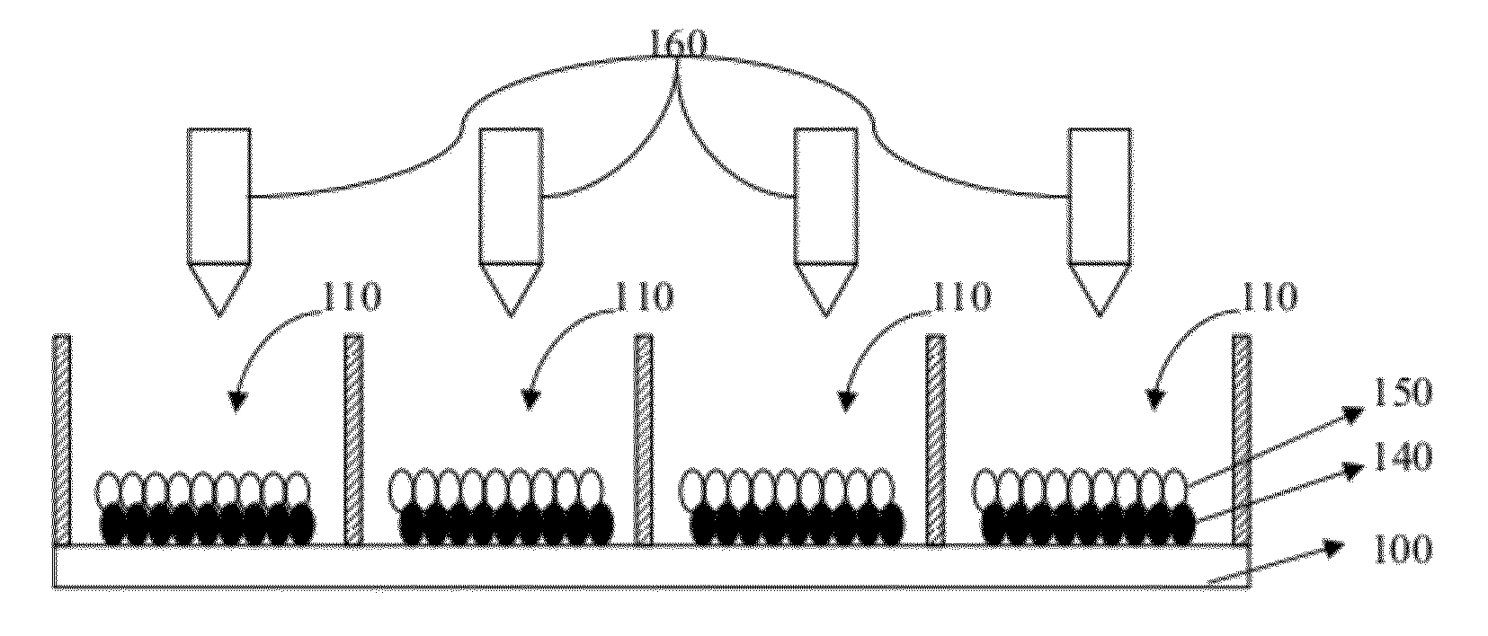
[0058](3) The pigment particles are colored after filling of the particles, and some of the pigment particles are configured to have special reaction selectivity for selectively reacting or bonding with only specific colorants (or its precursors and derivatives) so that some particles react with the specific colorants to change color, while the other pigment particles do not react with the colorants, thereby maintaining the color. This simplifies the formation process of the color pigment particles, thereby reducing costs. Further, the pigment particles of different colors would not mix together during the filling process to cause color deviation.
[0059](4) The pigment particles are charged after filling of the particles, and some of the pigment particles are configured to have chemical inert surface reaction characteristics, while the other is configured to have reaction selectivity, such that when they are in contact with the charge controlling agent, the pigment particles with the reaction selectivity react with the charge controlling agent, while the other pigment particles do not react with the charge controlling agent because of the chemical inert surface reaction characteristics. Therefore, in the particle filling process, no particle aggregation occurs, which enables the pigment particles to be filled uniformly in the cells.

Problems solved by technology

The manufacturing process of the color filter is highly complicated and sophisticated, resulting in high manufacturing cost of the color microcapsule electrophoretic display that cannot be reduced.
Also, the design of the microcapsule electrophoretic display is restricted due to the existence of the color filter in the display structure.
Further, the color filter reduces reflectivity of light from the environmental light source so that the color saturation of the display is reduced.
However, the chemical structure of the colorants and the charge controlling agent generally contains a functional group with a rapid response and reaction selectivity or ionicity, and may participate in and complicate the polymerization.
Thus, the pigment particles formed may have a wider range distribution of the particle diameter and non-uniformity of shape, thereby reducing or eliminating the production of the particles.
In addition, the colorants and the charge controlling agent have relatively larger particles, which are more difficult to disperse or dissolve in the solutions, and thus difficult to be uniformly coated or distributed among the particles.
Thus, the color pigment particles formed may have non-uniformity of color or charge distribution, thereby increasing the difficulties of forming color pigment particles by the chemical synthesis method.
In the polymer compounding process, the colorants and the charge controlling agent may not be uniformly distributed in the resin, and the high temperature environment may destroy the structures of the colorants and the charge controlling agent.
Thus, the color pigment particles formed may have non-uniformity of color or charge distribution.
Further, the pigment particles formed by pulverization may have a wider range distribution of the particle diameter, non-uniformity of shape and rough surfaces, thereby increasing the particle aggregation and difficulties to control the movement of the pigment particles in the air or the solutions.
The uniformity of the particle size and shape can be achieved by classification of particle diameter and rounding, but the particle yield is thus reduced, thereby increasing the production cost.

Method used

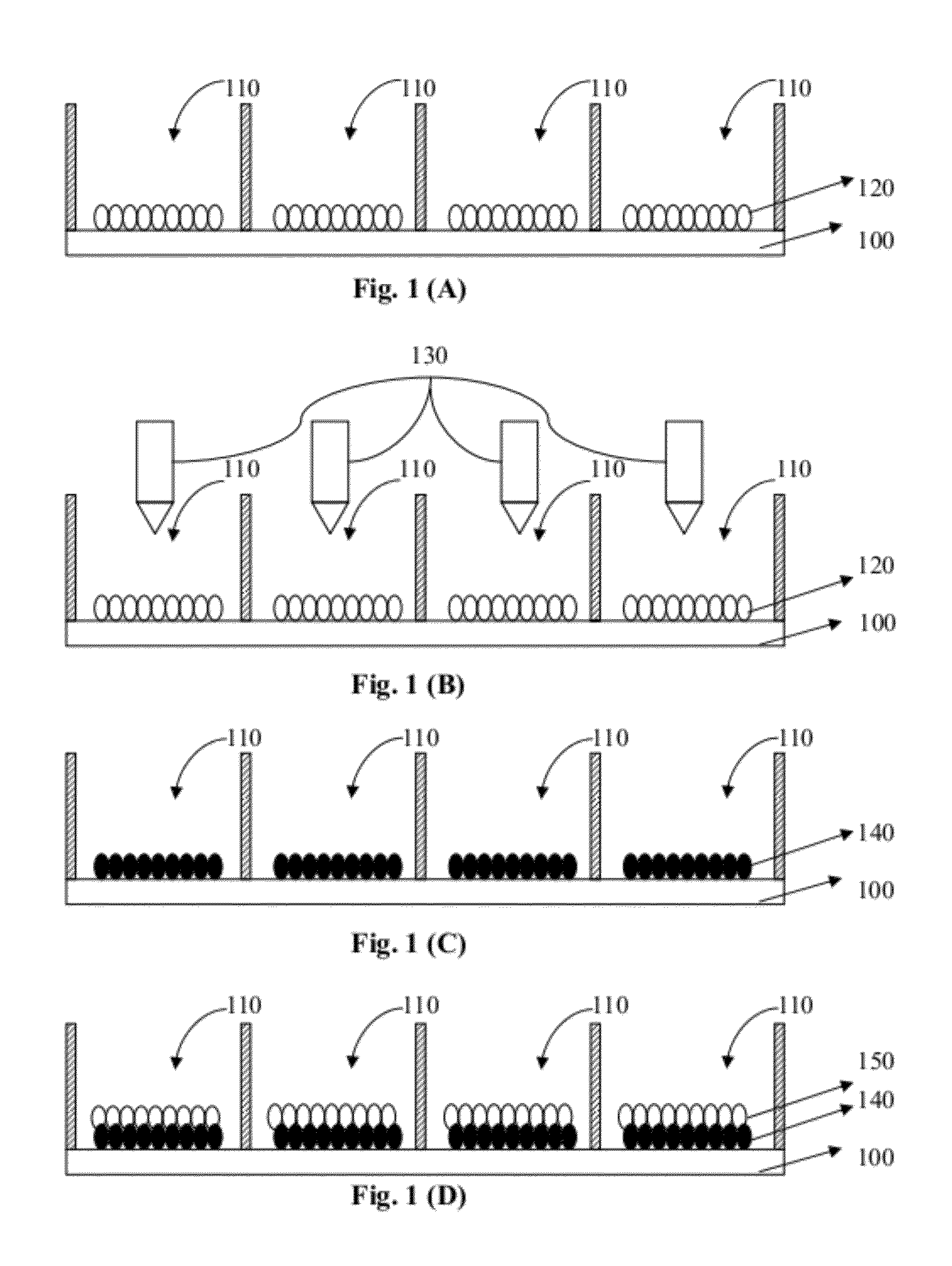
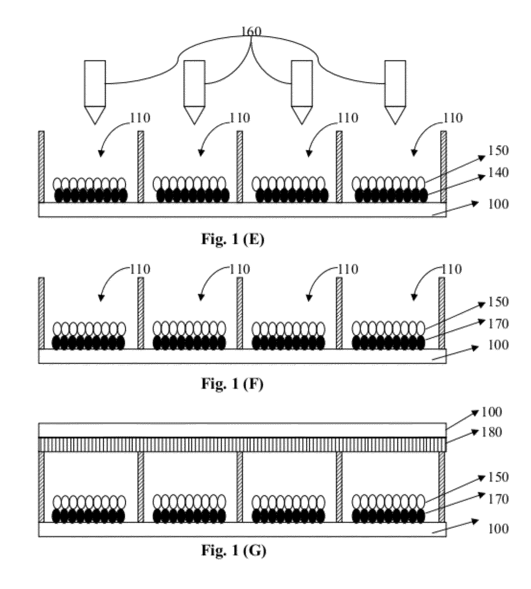

Image

  • Switchable color particle-based display and method of manufacturing same
  • Switchable color particle-based display and method of manufacturing same
  • Switchable color particle-based display and method of manufacturing same

Examples


example 1

[0138]Desired amounts of polyvinyl pyrrolidone (Sigma-Aldrich), 2-2′-azobis (2-methyl-butyronitrile) (TCI), vinyl aniline (Alfa-Aesar), divinylbenzene (Aldrich) and styrene (Acros) are added into an amount of ethanol and completely dissolved therein to form a first liquid mixture, which is then disposed in a high temperature environment for polymerization for a period of time. Then, separating and drying processes are performed to obtain first-type particles with a particle size (D50) about 3.0 μm.

[0139]In addition, desired amounts of polyvinyl pyrrolidone (Sigma-Aldrich), 2-2′-azobis (2-methyl-butyronitrile) (TCI), 1H,1H,2H,2H-heptadecafluorodecyl methacrylate (Matrix), divinylbenzene (Aldrich) and styrene (Acros) are added into an amount of ethanol and completely dissolved therein to form a second liquid mixture, which is then disposed in a high temperature environment for polymerization for a period of time. Separating and drying processes are then performed to obtain particles. ...

example 2

[0141]Desired amounts of polyvinyl pyrrolidone (Sigma-Aldrich), 2-2′-azobis (2-methyl-butyronitrile) (TCI), vinyl aniline (Alfa-Aesar), divinylbenzene (Aldrich) and styrene (Acros) are added into an amount of ethanol and completely dissolved therein to form a first liquid mixture, which is then disposed in a high temperature environment for polymerization for a period of time. Then, separating and drying processes are performed to obtain first-type particles with a particle size (D50) about 3.0 μm.

[0142]In addition, desired amounts of polyvinyl pyrrolidone (Sigma-Aldrich), styrene (Acros), vinyl pyridine (Aldrich) and azobisisobutyronitrile (Showa) are added into an amount of ethanol and completely dissolved therein to form a second liquid mixture, which is then disposed in a high temperature environment for polymerization for a period of time. Then, separating and drying processes are performed to obtain polystyrene-vinyl pyridine particles. Further, the obtained particles, acrylic...

example 3

[0144]Polyvinyl pyrrolidone (Sigma-Aldrich), 2-2′-azobis (2-methyl-butyronitrile) (TCI), vinyl aniline (Alfa-Aesar), divinylbenzene (Aldrich) and styrene (Acros) are added into an amount of ethanol and completely dissolved therein to form a first liquid mixture, which is then disposed in a high temperature environment for polymerization for a period of time. Then, separating and drying processes are performed to obtain first-type particles with a particle size (D50) about 3.0 μm.

[0145]In addition, polyvinyl pyrrolidone (Sigma-Aldrich), 2-2′-azobis(2-methyl-butyronitrile) (TCI), 1H,1H,2H,2H-heptadecafluorodecyl methacrylate (Matrix), divinylbenzene (Aldrich) and styrene (Acros) are added into an amount of ethanol and completely dissolved therein to form a second liquid mixture, which is then disposed in a high temperature environment for polymerization for a period of time. Then, separating and drying processes are performed to obtain particles. The obtained particles are then coated...


PUM

PropertyMeasurementUnit
surface energyaaaaaaaaaa
diameteraaaaaaaaaa

Abstract

The invention in one relates to a method for manufacturing a switchable particle-based display having a plurality of display units spatially arranged in a matrix form, wherein each display unit comprises one or more cells. In one embodiment, the method includes filling a plurality of first-type particles into the one or more cells of each display unit, filling one or more solutions into the one or more cells of each display unit, respectively, so that each cell contains one of the one or more solutions, where each of the one or more solutions comprises a respective colorant, and the respective colorant in each cell reacts with or adsorbs on the first-type particles therein, and filling a plurality of second-type particles into the one or more cells of each display unit.

Description

CROSS-REFERENCE TO RELATED PATENT APPLICATION[0001]This application is a continuation-in-part of U.S. patent application Ser. No. 13 / 167,927, filed Jun. 24, 2011, entitled “SWITCHABLE PARTICLE-BASED DISPLAY AND METHOD OF MANUFACTURING SAME” by Rong-Chang Liang, Jiunn-Jye Hwang, Jung-Yang Juang, and Min-Chiao Tsai, the disclosure of the above identified co-pending application is incorporated herein by reference in its entirety.[0002]Some references, if any, which may include patents, patent applications and various publications, are cited and discussed in the description of this invention. The citation and / or discussion of such references is provided merely to clarify the description of the present invention and is not an admission that any such reference is “prior art” to the invention described herein. All references cited and discussed in this specification are incorporated herein by reference in their entireties and to the same extent as if each reference was individually incorpo...

Claims


Application Information

Patent Timeline
Patent Type & Authority Applications(United States)
IPC IPC(8): H01J9/26H01J9/00G02F1/167G02F1/1679
CPCG02F1/167G02F2001/1678G02F2001/1672G02F1/1681G02F1/1679
Inventor LIANG, RONG-CHANGHWANG, JIUNN-JYEJUANG, JUNG-YANGXU, YA-ZHUYANG, CHIEH-WEN
Owner DELTA ELECTRONICS INC
Why Eureka
Try Eureka