
Rocket Launch System and Supporting Apparatus

a technology of rocket launch system and supporting apparatus, which is applied in the direction of rocket/towing gear, cosmonautic vehicles, nuclear elements, etc., can solve the problems of reducing the amount of power that actually reaches the climbing vehicle, and supplying the vehicle climbing the cable with sufficient energy. , to achieve the effect of reducing the mass of material

Active Publication Date: 2013-01-10
CHIN +1
View PDF47 Cites 26 Cited by
  • Summary
  • Abstract
  • Description
  • Claims
  • Application Information

AI Technical Summary

Benefits of technology

The patent text describes a need for a way to deliver useful materials to the upper atmosphere or beyond, such as propellants and gases for life support, at a much lower cost per unit mass than currently available. The method should also use currently available materials and technologies and be eco-friendly by minimizing the mass of material used to propel the vehicle out of the earth's atmosphere using renewable sources of energy like hydroelectric, geothermal, or solar photovoltaic.

Problems solved by technology

The primary difficulty with this latter method is that the tensile strength of the material required for the cable far exceeds any existing material, especially since the self weight of the cable would be considerable.
Another difficulty is to supply the vehicle climbing this cable with sufficient energy to essentially climb out of the majority of the earth's gravitational field.
A weightless, super strong, cable material would be ideal for such a “space elevator” but, this does not yet exist.
Also, the problem of energy supply up thousands of miles of cable has prompted the consideration of beamed microwave or laser power to the climbing vehicle.
The defocusing and obstructive effect of clouds and the atmosphere on the beamed power is likely to greatly reduce the amount of power that actually reaches the climbing vehicle.
Dissipation of energy on the return of the (climbing) vehicle to the earth is likely to be quite wasteful because of the need for braking to prevent it from exceeding the speed capacity of the mechanism holding the said vehicle to the cable.
Many of the current proposed methods require the development of new materials or massive structures and are unlikely to see commercial service for many decades to come, if ever.
This use of non-renewable resources is inherently inefficient because at each stage of production of the fuels there is a compounding of process inefficiencies.
As well, the large mass and sometimes toxic nature of exhaust material used to propel the vehicle out of the atmosphere frequently does ecological damage or may cause climatological disturbances.
These, with the exception of the ground based stations, cannot provide more than a relatively brief period of atmospheric data sampling.
Many of these methods of atmospheric monitoring also utilize single use instrument packages, while existing ground based stations cannot obtain physical samples to determine the chemical composition, the bacterial / viral content, or the intensity and spectral analysis of sunlight and other data throughout the depth of the atmosphere.
The extreme high altitude cases of this are the INMARSAT and IRIDIUM satellite phone systems which utilize extremely expensive and unrepairable geostationary satellites for telecommunications.
Indeed, recently there has also been increasing non-military interest in expensive high altitude airplane flights.
A problem with Space Ship One and Space Ship Two is that their rocket motors uses a liquified nitrous oxide oxidiser and hydroxyl terminated polybutadiene solid fuel, which solid fuel produces an exhaust which includes soot, partially burnt rubber and other noxious materials.
It is likely that, although these are cheap fossil fuels, combustion will not be complete.
Further, the altitude from which skydivers have been jumping from has been on the increase, although this has been limited by two major factors.
These are the limited capability of civilian fixed wing airplanes and helicopters to operate at higher altitudes where there exists a civil aviation half hour limit for oxygen enriched breathing systems or, a requirement for a pressurized suit or cabin.
However, the engines of such aircraft, designed to operate efficiently at higher Mach numbers have been reported to require the attainment of a velocity in excess of three times the speed of sound for them to start.
Considerable complexity, with a concomitant weight penalty is required for an engine to operate in the various flight regimes from stationary to hypersonic.
In 2003, the manned space shuttle Columbia of the United States of America was destroyed upon re-entry into the earth's atmosphere, due to structural damage which occurred during the launch phase.
As well, over time, there has also been an accumulation of orbital craft in need of repair; and distressed orbital craft, and objectionable and dangerous debris which needs to be removed from orbit.
Since craft such as the Columbia space shuttle of the United States are heavy, and they lack main engines that can operate for significant lengths of time after re-entry due to the hazards and weight penalties of carrying cryogenic or other fuels for use on the return flight in atmosphere, these craft must leave orbit at specific points if they are to be able to glide to the few airports with runways of sufficient strength and length which exist close to its orbital track.
As the Indonesian tsunami disaster unfolded in December 2004, it was clear that reconnaissance of many of the affected areas and subsequent delivery of initial relief supplies did not occur until days or even weeks after the event, with the consequence that many tens of thousands died, more than if early relief had been available.

Method used


Image

  • Rocket Launch System and Supporting Apparatus
  • Rocket Launch System and Supporting Apparatus
  • Rocket Launch System and Supporting Apparatus

Examples


Embodiment Construction

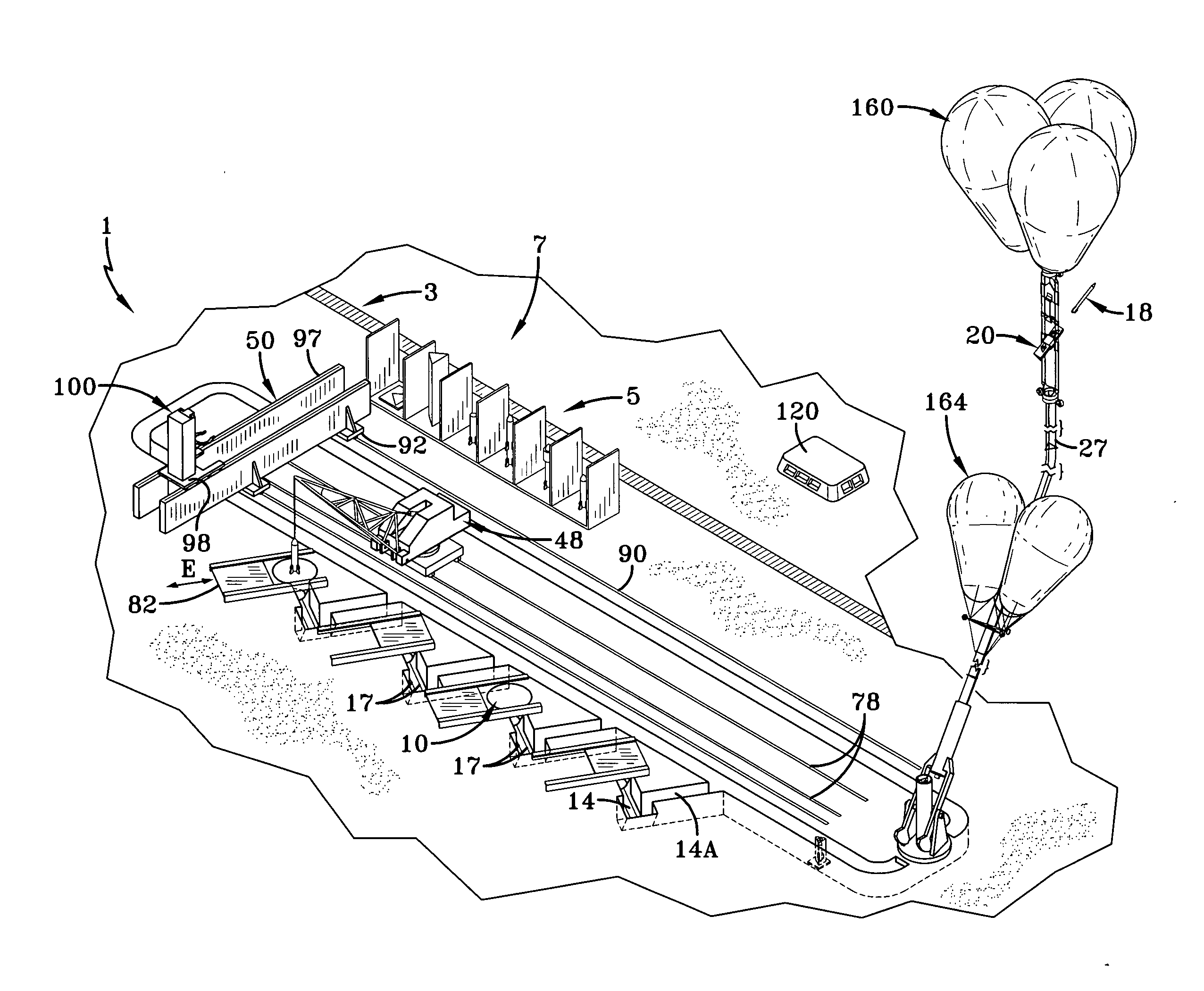
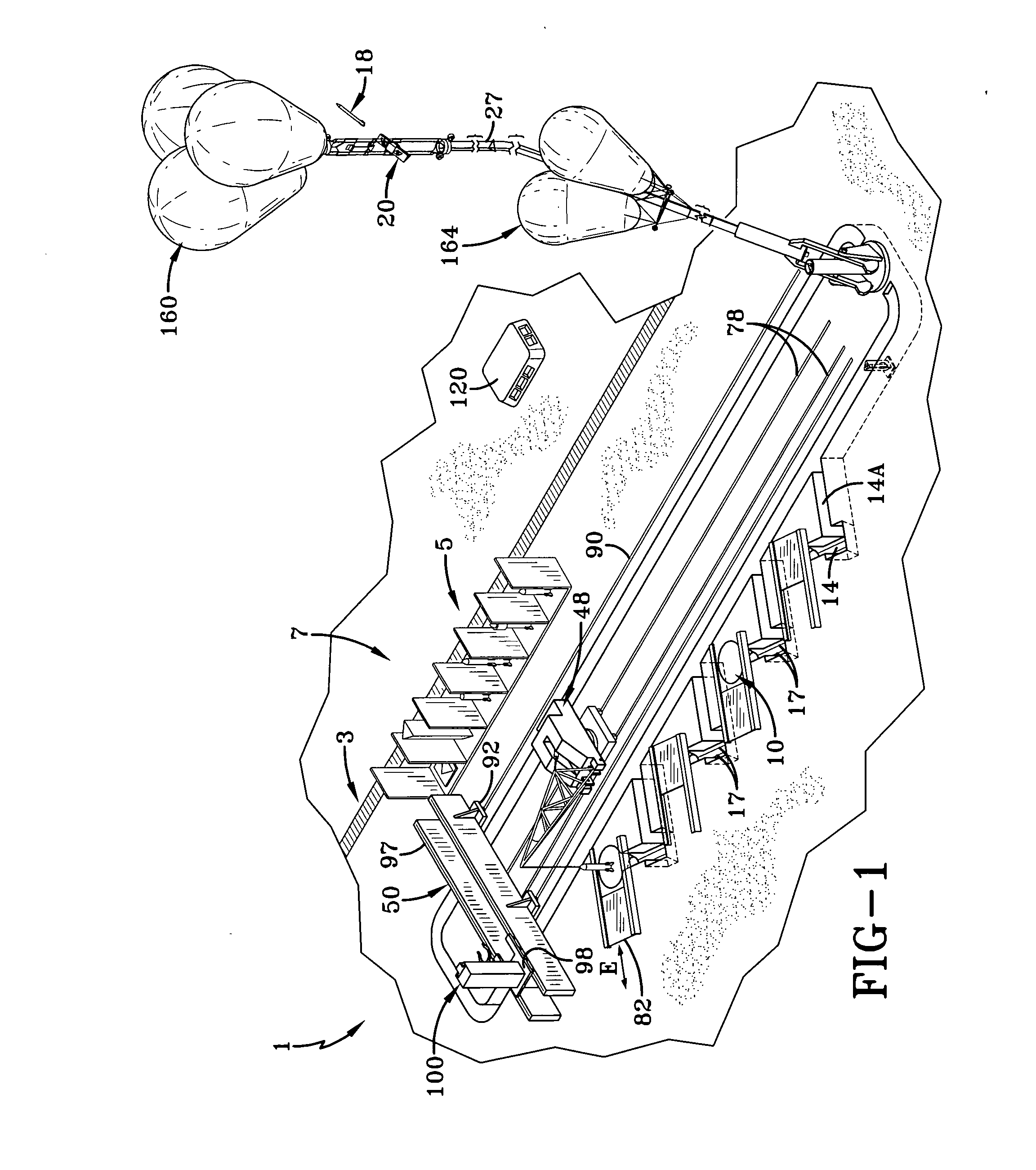
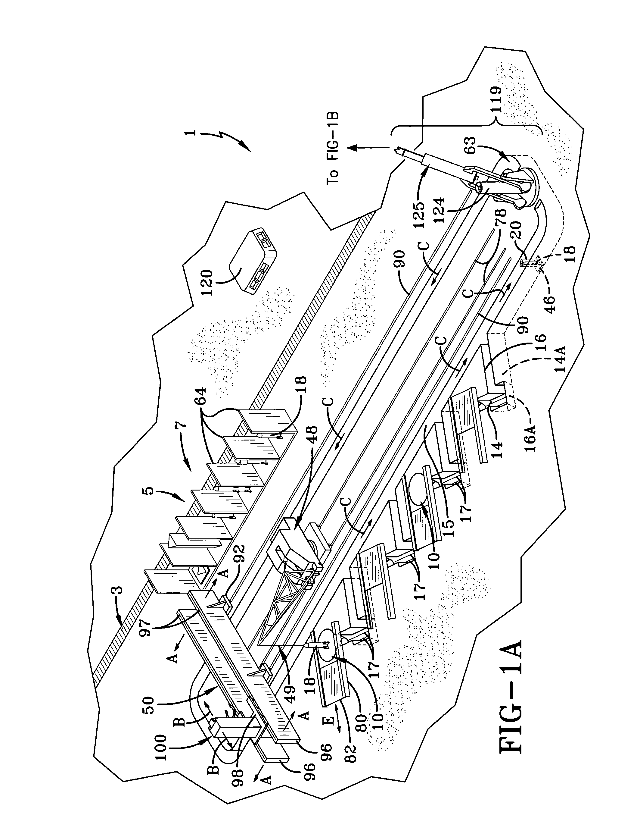
[0130]The preferred embodiment of the invention is initially described in general terms referring to some components described in more detail below. The general components are shown in such general terms in FIGS. 1, 1A and 1B. The preferred embodiment is a rocket launch system 1 which includes apparatus for moving a rocket 18 to be launched. Rocket 18 is first either in a container or rocket-transporting device such as a carriage 20 or is to be loaded into carriage 20, from storage racks 7. Carriages 20 have cylindrical lengthwise bores into open-ended continuous tubes 836 (FIGS. 13, 13C) which are disposed and held in place for receiving a rocket 18. Carriages 20 are weatherproof and have a longitudinal axis, which is the same longitudinal axis of tube 836. Rockets 18, components thereof, and carriages 20 which may or may not be loaded with rockets 18, are conveyed to storage racks 7 by an appropriate transport railing car on a railway 3 to an off loading area 5. A crane 48 carries...


PUM


Abstract

A rocket launch system (1) includes a tubular rocket launcher carriage (2) with electromotive cableway traction drives (26) conveyed beneath a two axis pivot (63) anchored to the earth, elevated into a co-axial transfer tube (124, 143) leading to three primary tether cables (27) whose weight is offset by balloons (164). The carriage is conveyed to a docking station (166) supported into the stratosphere by a pair of secondary cables (184) suspended under an attachment frame (162) for tensioning balloons. The carriage is engaged by a carriage end gripper (196) guided by two secondary and two tertiary cables (186) and lifted by a lower hoist (198) guided by the secondary cables. This lower hoist is supported by an upper hoist (168) suspended from the tensioning balloons attachment frame. The carriage, which engages a lift ring (183) guided by two secondary cables, is elevated further, rotated as desired, with rocket release and nearly recoilless ejection during freefall of the carriage, with engine ignition occurring at a safe distance.

Description

CROSS REFERENCE TO RELATED APPLICATION[0001]This application claims the benefit of U.S. provisional patent application Ser. No. 61 / 337,645 filed Feb. 11, 2010, under Title 35, United States Code, Section 119(e), which is incorporated herein by reference in its entirety.BACKGROUND OF THE INVENTION[0002]1. Field of the Invention[0003]The present invention relates to a system for delivering various types of payloads to the upper atmosphere and beyond, and more particularly to a high cyclic rate launch rate rocket launcher with an upper launch station. The cables' self weight is offset by lighter-than-air balloons. The cables are tensioned by one or more lighter-than-air balloons and anchored by a pivoting tether.[0004]2. Description of the Prior Art[0005]Many methods of delivering useful materials such as propellants, gases for life support, etc. and fabricated items to the upper atmosphere or beyond, exist or have been proposed in recent publications.[0006]These primarily involve rock...

Claims


Application Information

Patent Timeline
IPC IPC(8): B64G6/00B64G1/14B64G5/00B64F1/04F41F3/04
CPCB64G1/005F41F3/06B64G2001/643B64G6/00F41F3/04B64G1/643A42B3/20F41F7/00
Inventor CHINCARRAHA, KIMBERLY A.
Owner CHIN
Learn More