Cryogenic specimen holder

a specimen holder and cryogenic technology, applied in the field of cryogenic specimen holders, can solve the problems of affecting imaging and analysis, introducing physical stresses on the device, and vibrations formed by turbulence in the medium, so as to improve imaging and analytical information quality, enhance specimen cooling, and reduce volume

Active Publication Date: 2013-01-17
STABACINSKIENE HALINA +5
View PDF4 Cites 37 Cited by
  • Summary
  • Abstract
  • Description
  • Claims
  • Application Information

AI Technical Summary

Benefits of technology

[0017]A cryogenic specimen holder is disclosed for a variety of imaging and analytical applications. The holder improves the quality of imaging and analytical information by overcoming major challenges related to holder drift and vibration. In accordance with one embodiment of the invention, a specimen holder includes a Dewar for receiving and storing a cooling medium, such as liquid nitrogen. The Dewar is constructed as a conventional vacuum flask with an interposed partial vacuum between an inner liquid support vessel and an outer protective housing. A set of thermal conductor ribbons, braids or the like, preferably flexible, including combinations thereof, are incorporated into the thermal transfer system which extracts heat from the specimen. In one embodiment, one such member is attached to the lowest point of the Dewar. The other end of this assembly is connected to a conductor rod which is in thermal contact with the sample cartridge. A similar flexible assembly may form the thermal junction between the conductor rod and the cartridge housing. Each of the thermal ribbons, for example, in the preferred embodiment, forms a vibration damper between the various components of the cooling assembly. Additional points of thermal contact may also be utilized to enhance cooling of the specimen. In the preferred embodiment, a secondary, insulating cooling conduit is formed from at least one non-structural tube, which extends throughout the length of the holder shaft. Longitudinal manipulation of the specimen is accomplished with a separately cooled actuation rod extending within the primary cooling conduit which provides additional cooling for the specime...

Problems solved by technology

This is because it is desirable to maintain the ice component of the specimen in an amorphous state below −155° C. Above −155° C., the ice will adopt a crystalline form, which is detrimental to imaging and analysis.
During transfer and while the specimen holder is not inserted into the imaging or analysis device, it is also essential to physically protect the specimen, as it is highly vulnerable to physical and environmental damage and/or contamination from water vapor and other sources.
As the liquid nitrogen or other cooling medium boils off under ambient atmospheric conditions, vibrations are formed by the turbulence in the medium.
The rigid contact between the Dewar and the cooling assembly of the prior art devices further introduces physical stresses on the device during thermal expansion and contraction.
Most Dewar devices are open to ambient atmosphere to permit the boil off of the liquid medium and to minimize the retention of expanding warm gas medium, which has deleterious effects relating to pressure within the vessel.
The ability to increase the tilt of the specimen holder is limited, however, by the possibility of spillover of the liquid medium from the Dewar, as well as a thermal gradient induced into the walls of the container, which create unsatisfactory results, including vibrations, drift and, potentially, spilled liquid nitrogen in the laboratory.
Avoidance of this condition substantially limits the ability to tilt the specimen.
The thermal gradient present between the Dewar and the specimen cartridge, as a function of distance and time, as well as changing environmental conditions along the length of the holder, causes unpredictable and dynamic dimensional changes, resulting in specimen drift from the nominal position within the imaging device.
Moreover, any thermal contact between the conductor assembly, which extends within, but dimensionally separate from the outer holder ba...

Method used


Image

  • Cryogenic specimen holder
  • Cryogenic specimen holder
  • Cryogenic specimen holder

Examples


second embodiment

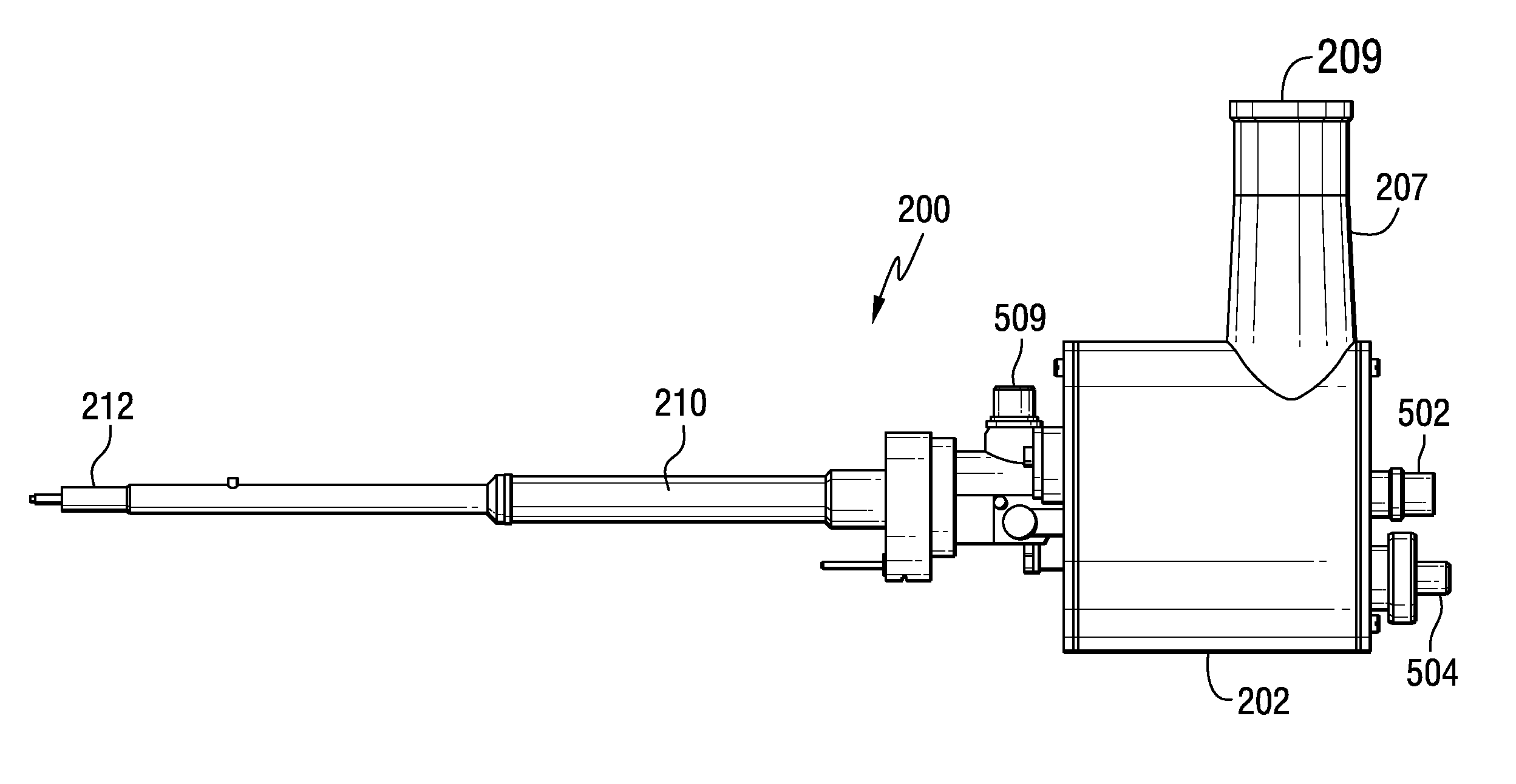
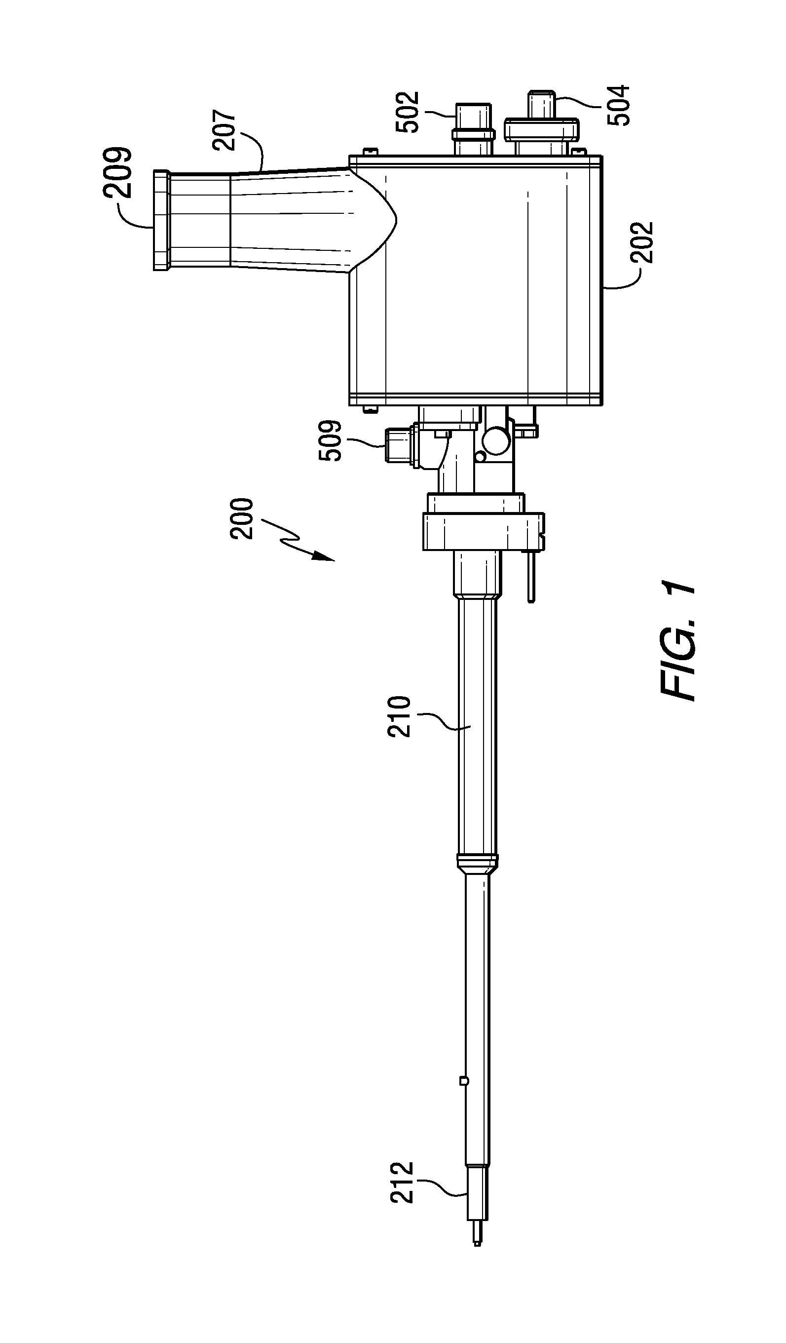
[0046]Referring again to FIG. 2a, conductor rod 505 and conductor conduit are received and supported by bellows assembly 511. Bellows assembly 511 is a flexible, insulating assembly for structurally supporting, at the tip end 508a, the Dewar end of conductor conduit 505a, and at the support end 508b, the dewar end of conductor rod 505 within barrels 210, 212. Additionally, bellows assembly 511 is intended to separate evacuated space 211 from the remainder of the holder. Evacuated space 211 includes a vacuum controlled by the user through valve 504. Barrels 210, 212 are alternatively vented to ambient pressure while the holder is not in use, with the interior space of barrels 210, 212 being evacuated by the microscope pumping mechanism while inserted in the goniometer and in use.

[0047]Referring now to FIGS. 4a-4e, front barrel 212 is provided with an independent front insulating tube 258 which is spatially isolated from front barrel 212, preferably constructed of a non-magnetic nicke...

first embodiment

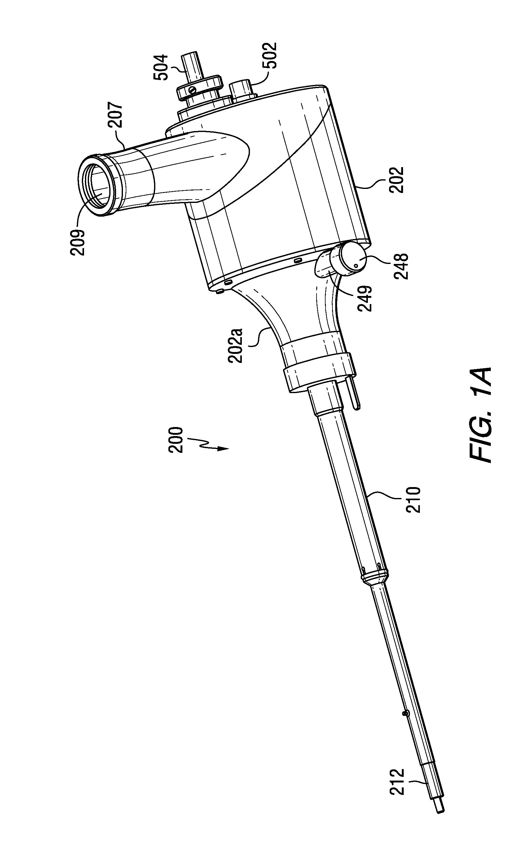
[0053]With additional reference to FIGS. 2, 3 and 3a, actuation assembly 249 is affixed to the end of actuator rod 240 proximate to the housing 202. Actuator rod 240, which may be optionally comprised of several components or modules interconnected with each other, extends within the interior space of middle barrel 210 and front barrel 212 to terminate with actuator pin 242 at the operative end of the device in order to displace specimen cartridge 232. As will be appreciated by those skilled in the art, such displacement may be in any direction or dimension. Specimen cartridge 232 is adapted for slidable displacement in a lateral direction in and out of cartridge housing 506 when a lateral force is applied to the actuator rod 240 by turning rotational knob 248. Knob 248 is affixed to actuator shaft 252 which is rotatably mounted within handle 249. O-ring seal 251 is utilized to separate the interior of the holder assembly 200, which may be under vacuum conditions, from the ambient a...

third embodiment

[0055]In actuator assembly 249, as illustrated in FIGS. 2b-2d and 3c, actuation assembly 249 is affixed to the end of conductor rod 505 proximate to the housing 202. Knob 248 is affixed to actuator shaft 252 which is rotatably mounted. O-ring seal 251′ is utilized to separate the interior of the holder assembly 200, which may be under vacuum conditions, from the ambient atmosphere. It is noted that actuator shaft 252 is rotated to engage and adjust pinion gear 1001 with respect to rack gear 1004 and that the rotational motion of knob 248 causes lateral displacement of rack gear 1004, conductor rod 505 and conductor isolation rod 238c, which is affixed to rack gear 1004 by clamp 1005. Conductor rod 505 is slidingly supported and thermally isolated by conductor isolation rod 238c. O-ring 1003 provides a sealing interface between the interior of actuation housing 1002 and the interior of holder 200. The interior of actuation housing 1002 is evacuated by the TEM device, while the interi...


PUM


Abstract

An improved cryogenic specimen holder for imaging and analysis facilitates imaging at very high tilt angles with a large field of view. A retractable specimen holder tip protects the specimen during transport. An optimized Dewar design is positioned at a fixed, tilted angle with respect to the axis of the holder, providing a means of continuously cooling the specimen irrespective of the high tilt angle and amount of liquid nitrogen present in the vessel. The Dewar neck design reduces entrapment of nitrogen gas bubbles and its shape prevents the spilling of liquid nitrogen at high tilt angles. The specimen holder has a retractable tip that completely encapsulates the specimen within a shielded environment internal to the specimen holder body. The cooling and specimen transfer mechanisms reduce thermal drift and the detrimental effects of vibrations generated by both the evaporation of liquid nitrogen present in the Dewar and other environmental effects.

Description

CROSS REFERENCE TO RELATED APPLICATION[0001]This application is a continuation-in-part of Stabacinskiene, et al., U.S. patent application Ser. No. 12 / 845,486, filed Jul. 28, 2010. It claims the benefit of United States Provisional Patent Application No. 61 / 515,359, filed Aug. 5, 2011.BACKGROUND OF THE INVENTION[0002]1. Field of the Invention[0003]This invention relates to specimen holders for maintaining a specimen at a low temperature during visualization, imaging or analysis. More specifically, it relates to holders utilized for transmission electron microscopy (TEM) and particularly to the Dewar used for the containment of liquid nitrogen and the subsequent cooling of the TEM specimen placed on a retractable cartridge and positioned within a cryogenically cooled shield.[0004]2. Description of the Prior Art[0005]There are a variety of imaging technologies which have been developed to observe and analyze specimens at the molecular and / or atomic level. These include optical, electro...

Claims


Application Information

Patent Timeline
IPC IPC(8): F25B49/00
CPCG01N23/20033G01N2223/612H01J2237/204H01J2237/2001H01J2237/0216H01J37/26H01J2237/20207H01J37/20B01L7/50
Inventor STABACINSKIENE, HALINAGRONSKY, JEFFREY J.THOMAS, CHRISTINE M.DESHMUKH, PUSHKARRAJ V.ROBINS, ALAN C.FISCHIONE, PAUL E.
Owner STABACINSKIENE HALINA
Why Eureka
Try Eureka