Seal gas monitoring and control system

a technology of monitoring and control system and sealing gas, which is applied in the direction of fluid tightness measurement, lighting and heating apparatus, instruments, etc., can solve the problems of failure of sealing system, lack of clean and dry sealing, operation loss and delay in start-up

Active Publication Date: 2013-02-07
JOHN CRANE INC
View PDF8 Cites 38 Cited by
  • Summary
  • Abstract
  • Description
  • Claims
  • Application Information

AI Technical Summary

Benefits of technology

[0012]The system of this disclosure is intended to eliminate the liquid condensate from the seal environment, thereby avoiding the lea

Problems solved by technology

A known cause of seal failure is a lack of clean and dry seal or buffer gas being supplied to the compressor.
Liquid contamination has been found to be a leading cause of the failures.
Initial gas composition information is often unreliable, and changes with time, resulting in failures due to liquid condensation.
Unexpected seal failures cause operational loss and delay in start-up.
Also, initial system selection often sabotages optimal reliability.
Compressor manufacturers often do not review the make-up of the process fluid,

Method used


Image

  • Seal gas monitoring and control system
  • Seal gas monitoring and control system
  • Seal gas monitoring and control system

Examples


Embodiment Construction

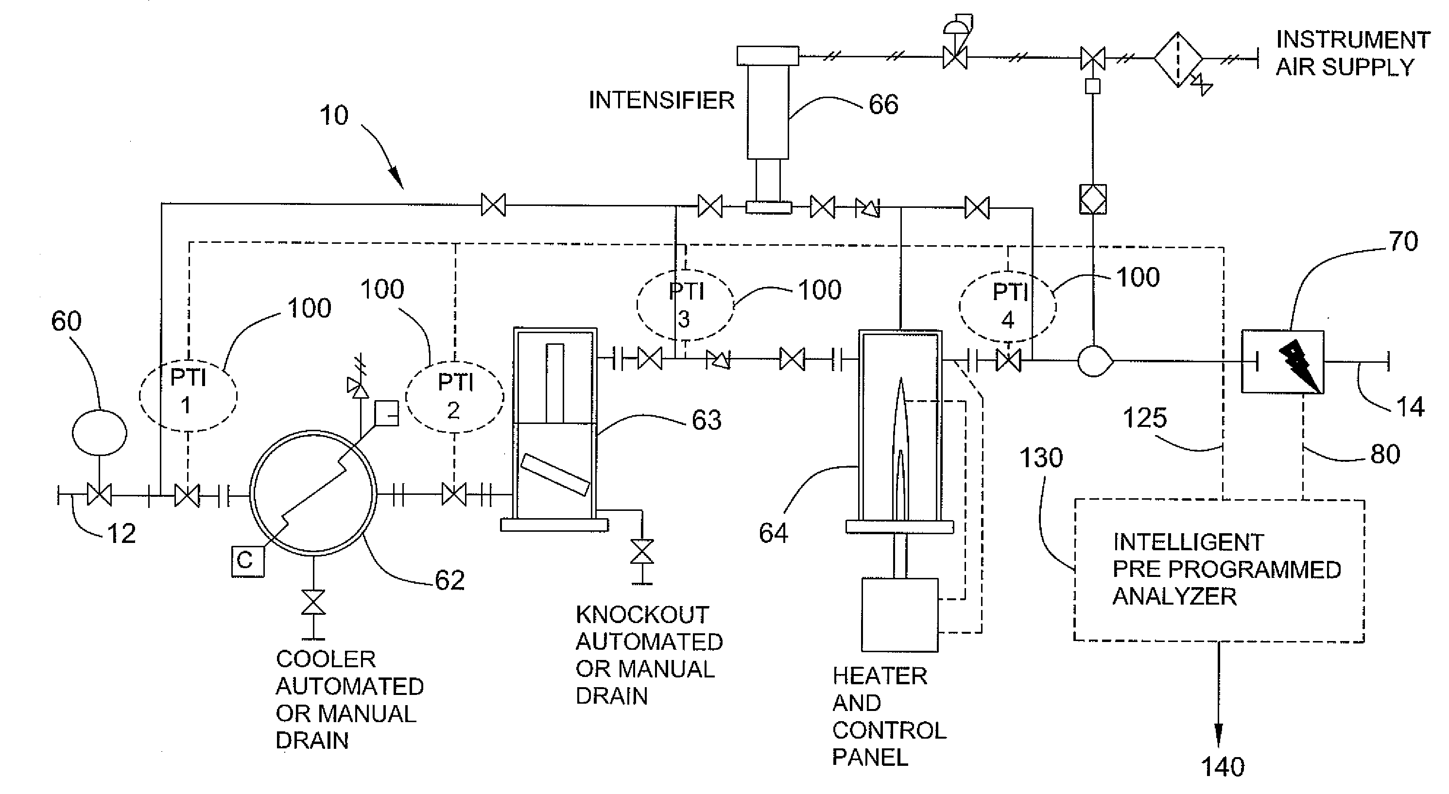
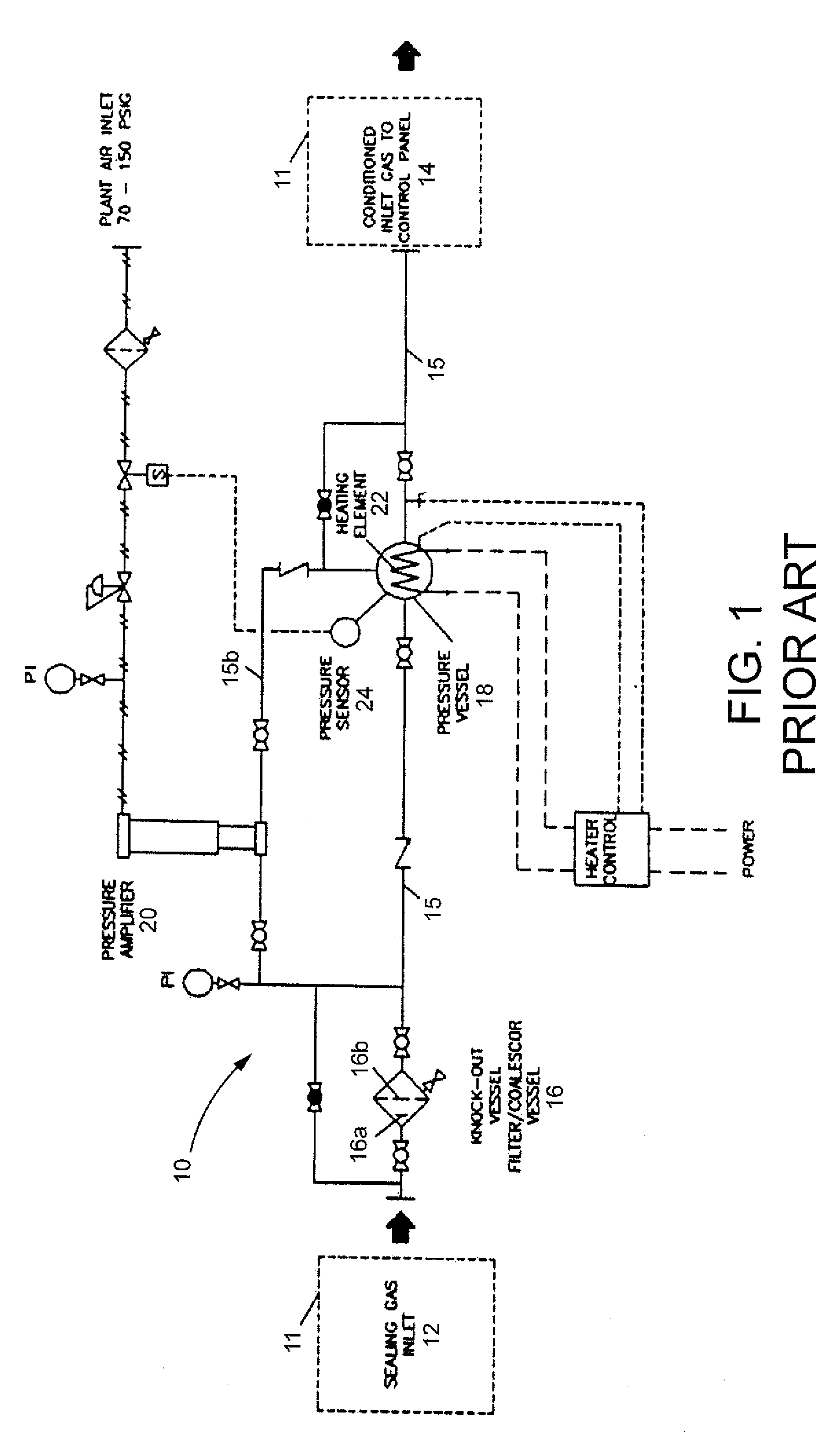
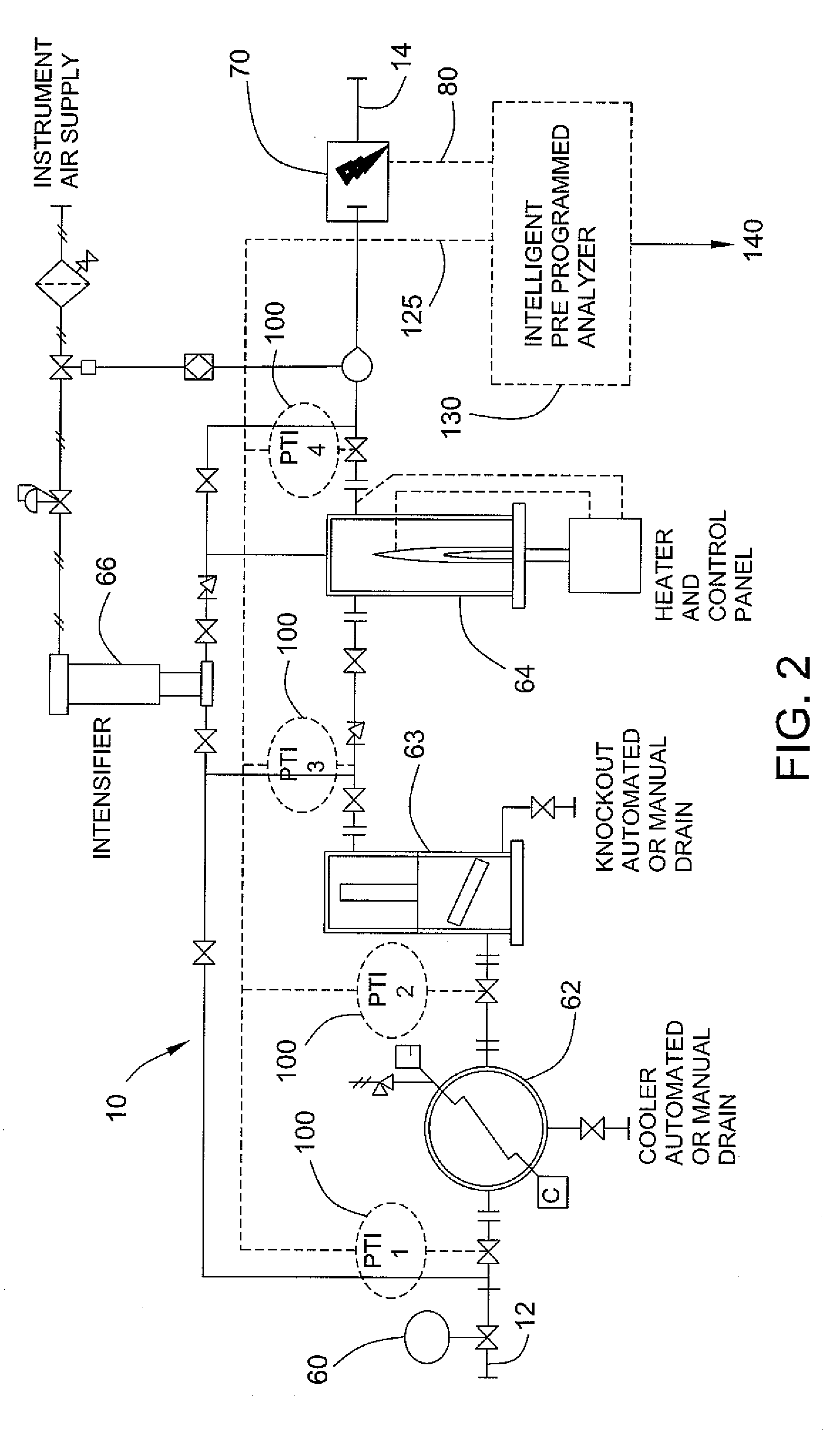
[0017]Commonly, seal gas conditioning consists of three functions—filtration, pressure or flow regulation, and leakage monitoring.

[0018]Filtration: In early designs, filtration consisted of simple duplex filters—one active filter and another on standby. A simple valve would reposition each filter to facilitate the filter element replacement. A supply gas line from the discharge side of the compressor then fed the warm discharge gas to the filter. The coalescent or particulate type gas filters used in this application are not always effective to completely purge liquid and condensate from the seal gas stream.

[0019]Pressure or Flow Regulation: The warm gas from the filter is pushed across a pressure regulator or flow control valves to supply clean buffer gas to the seal environment. The buffer gas pressure is normally lower than the discharge pressure, and must be higher that the compressor's suction pressure. By reducing the buffer gas pressure across the regulator valve, the gas exp...


PUM


Abstract

A monitoring and control system for a seal gas supply system for a non-contacting gas seal. The supply includes several gas conditioning elements or units. The monitoring and control system includes an evanescent wave sensor to sense the presence of liquid in the seal gas. Multiple sensors to sense the temperature and pressure of the treated seal gas are disposed at the outlet of the conditioning elements. A programmable logic device is provided with information regarding the phase of the gas at various pressures and temperatures and compares the sensed data to the baseline data. Recognition of liquid concentrate results in an output signal.

Description

CROSS REFERENCE TO RELATED APPLICATIONS[0001]This application claims priority pursuant to Title 35 U.S.C. §19(e) to U.S. Provisional Application Ser. No. 61 / 514,732, filed Aug. 3, 2011 and entitled “Seal Gas Monitoring and Control System”, the entire specification and drawings of which are incorporated herein by reference as if fully set forth herein.BACKGROUND[0002]This disclosure relates to gas conditioning systems for non-contacting gas seals. More particularly, it relates to a system for monitoring and control of seal buffer gas.[0003]Non-contacting seals for gas compressors and other rotating equipment such as gas and steam turbines, turbo expanders, centrifugal pumps and the like, operate on a thin film of conditioned process gas; pre-treated to render it suitable for delivery to, and passage through, the seal mechanism. Commonly, the source of this seal gas, sometimes called buffer gas, is the machine discharge.[0004]The principle of dry gas seal technology is that the sealin...

Claims


Application Information

Patent Timeline
IPC IPC(8): G01M3/14
CPCF01D11/06F25B49/00F01D11/00F16J15/3492
Inventor DELRAHIM, JOEHOSKING, PAUL A.
Owner JOHN CRANE INC
Why Eureka
Try Eureka