Heat recovery system for pyrometallurgical vessel using thermoelectric/thermomagnetic devices

a pyrometallurgical vessel and heat recovery technology, applied in the manufacture/treatment of thermoelectric devices, lighting and heating apparatus, furnaces, etc., can solve the problems of inability to use coolants in close proximity to the pyrometallurgical vessel, inefficiencies in the conversion process, etc., to enhance the device performance, and improve the effect of efficiency

Inactive Publication Date: 2013-02-28
BHP BILLITON ALUMINUM TECH
View PDF0 Cites 12 Cited by
  • Summary
  • Abstract
  • Description
  • Claims
  • Application Information

AI Technical Summary

Benefits of technology

[0018]Additionally, suitable orientation of thermoelectric and magneto-thermoelectric devices in a magnetic field enhances the performance of these devices, due to the Nernst effect as well as a magnetic field dependence of certain of the properties of the thermoelectric materials themselves. The most suitable magnetic fields for enhancing the device performance are not generally located in the same areas as is most suitable for collecting the waste heat hence the need (in addition to safety concerns around explosion risks) to displace the secondary heat exchanger from the immediate proximity of the pyrometallurgical vessel.
[0019]The applicants are of the view that considerable gains in efficiency, safety and practical application can be achieved where the conversion phase of heat recovery from pyrometallurgical process vessels is separated from the collection phase of the recovery process. The collection phase of the process is contained within a primary heat exchanger, which is used to collect waste heat in a gaseous heat transfer fluid, such as air. The conversion phase of the heat recovery is then contained within a separate secondary heat exchanger containing thermoelectric elements which convert the collected thermal energy to electrical energy.

Problems solved by technology

While for practical reasons, this waste heat must be collected on or preferably within the process vessel shell, processing and conversion of the waste heat to more usable forms, notably electrical current, within or immediately around the pyrometallurgical vessel imposes several inefficiencies upon the conversion process.
For reasons of risk around explosive phase changes which can easily occur when liquids come into contact with liquid metal, these coolants cannot be used in close proximity to the pyrometallurgical vessel.

Method used


Image

  • Heat recovery system for pyrometallurgical vessel using thermoelectric/thermomagnetic devices
  • Heat recovery system for pyrometallurgical vessel using thermoelectric/thermomagnetic devices

Examples


Embodiment Construction

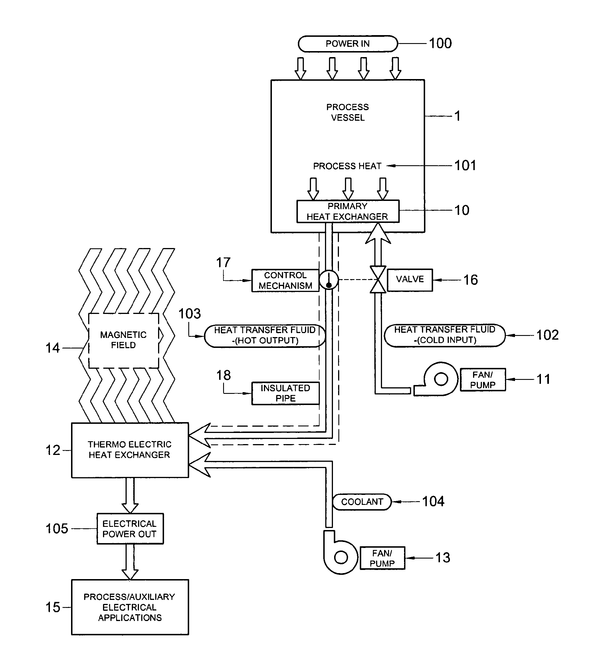
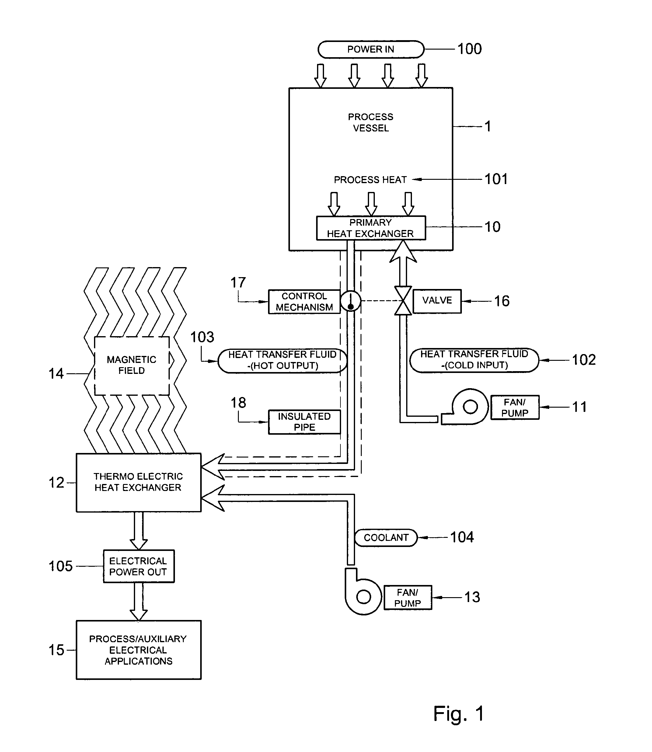
[0050]The invention will now be described with reference to its general use as a means of enhancing the efficiency of harvesting waste energy generated by pyrometallurgical process vessels. These efficiency improvements may relate to facilitating the safe use of heat transfer fluids having a higher heat capacity than the commonly-used gaseous fluids as a means of cooling the cold side of a thermoelectric array. These improvements may, where applicable (as for instance in equipment used for the electrolytic reduction of aluminium), relate to facilitating access to magnetic fields which would improve the recovery efficiency of thermoelectric devices by means of the Nernst effect or by material property improvements within the thermoelectric materials which may also be induced by the presence of a suitably-oriented magnetic field.

[0051]As shown in FIG. 1, pyrometallurgical process vessels (1) require a thermal energy input, designated as “Power In” (100) to develop the thermal and / or e...


PUM

PropertyMeasurementUnit
temperaturesaaaaaaaaaa
thermal energyaaaaaaaaaa
temperatureaaaaaaaaaa

Abstract

A method and apparatus for harvesting waste thermal energy from a pyrometallurgical vessel (1) and converting that energy to direct electrical current, the method including deriving and controlling a primary fluid flow (103) from a primary heat exchanger (10) associated with the pyrometallurgical vessel (1), providing a secondary heat exchanger (12) physically displaced from the pyrometallurgical vessel (1) which exchanges heat between the primary fluid flow (103) from the primary heat exchanger (10) and a secondary fluid flow (104). The secondary heat exchanger (12) has at least one thermoelectric or magneto-thermoelectric device having two operationally-opposed sides, the operationally-opposed sides being in thermal communication with the primary and secondary fluid flows (103,104) respectively. A temperature difference is maintained between the two operationally-opposed sides of the thermoelectric or magneto-thermoelectric device and electrical energy is generated from the temperature differential. The pyrometallurgical vessel preferably generates a magnetic field (14) in the region surrounding the pyrometallurgical vessel (1) and the secondary heat exchanger (12) having at least one magneto-thermoelectric device is positioned physically displaced from but within the magnetic field (14) surrounding the pyrometallurgical vessel such that the direction of temperature gradient across the secondary heat exchanger is oriented normally to the maximum principal direction of the magnetic field (14) and electrical energy is generated from the temperature differential and magnetic field via the Nernst effect or magneto-thermoelectric effects.

Description

FIELD OF THE INVENTION[0001]This invention relates to a method and apparatus for the recovery of waste heat from a pyrometallurgical vessel which may or may not generate a magnetic field during operation.BACKGROUND OF THE INVENTION[0002]Pyrometallurgical processes, which in the context of this invention refer to the thermal treatment of minerals, metallic ores and concentrates to bring about physical and / or chemical transformations in order to enable recovery of valuable metals, include but are not limited to drying, calcining, roasting, smelting, fuming and refining (including electrolytic processes). Processes at temperatures above about 100° C., have significant energy requirements, used for example, to maintain elevated temperatures. Some specific examples of pyrometallurgical processes having large energy demands include ore sintering, ore reduction / refining, and metal reduction / refining. These energy needs are often provided for by fossil fuel combustion or electricity. In mos...

Claims


Application Information

Patent Timeline
Patent Type & Authority Applications(United States)
IPC IPC(8): H01L37/04F27D17/00
CPCC22B1/00C22B9/00C22B21/00H01L37/00F27D19/00H01L35/30F27D17/004Y02P10/25H10N15/00H10N10/13
Inventor BAYER, INGOOLMSTEAD, BRUCE RINGSBY
Owner BHP BILLITON ALUMINUM TECH
Why Eureka
Try Eureka