Floor panel and methods for manufacturing floor panels

a technology of floor panels and dimensional stiffness, applied in the field of floor panels, can solve the problems of high impact sensitivity, limited bending stiffness and deformation, and development of ticking noise, and achieve the effect of reducing the risk of permanent impression, reducing the density, and sufficient dimensional stiffness

Active Publication Date: 2013-03-21
FLOORING IND LTD
View PDF3 Cites 104 Cited by
  • Summary
  • Abstract
  • Description
  • Claims
  • Application Information

AI Technical Summary

Benefits of technology

[0012]Preferably, said synthetic material board has an average density of 450 to 900 kilograms per cubic meter, preferably 500 to 600 kilograms per cubic meter. It is clear that the above-mentioned advantages of the preferred minimum density are more pronounced with a higher density of the foamed board material. However, too high a density will lead to disadvantageous effects, such as high impact sensitivity and increased sensitivity for possible unevennesses in the underlying surface, whereby sound boxes can be created, which effect an amplification of possible sound developed during the use of the floor covering.
[0013]Preferably, said synthetic material board has a local density on one or both flat sides which is higher than in a central layer of the foamed synthetic material board. With such construction, an optimal combination of an average low density and sufficient dimensional stiffness can be obtained. The locally higher density, preferably at least 5 or 10 percent higher than the average density, of course can be situated on the surface itself, as well as at a certain distance underneath the surface of the respective side, however, at a distance from a central layer of the substrate. In the cases where the locally higher density substantially is realized on one of both flat sides only, this preferably relates to the side of the substrate which is situated closest to said top layer. By means of such embodiment, the risk of the occurrence of permanent impressions can be minimized, while the floor panel as a whole has a low weight.
[0014]Preferably, said foamed synthetic material board relates to a foamed PVC (polyvinyl chloride) board, or a foamed synthetic material board which substantially consists of another vinyl compound, such as polyvinyl dichloride, polyvinyl butyrate, polyvinyl acetate and the like. As an alternative, as a basis material for the substrate use can also be made of melamine foam, polyurethane or polyisocyanurate.
[0015]According to a particular embodiment, said foamed synthetic material board is of the closed cell type, still better it relates to a closed cell foamed PVC board. It is known as such that with foamed synthetic material of the closed cell type the chambers of the foam practically are not interconnected, or at least to a much lesser extent than this is the case with foamed synthetic materials of the open cell type. A foamed synthetic material board of the closed cell type offers a very high stiffness, dimensional stability and water-resistance, with a limited density of, for example, 600 kilograms per cubic meter or less. The limited density offers interesting advantages in logistics, such as in transport. Also, the limited density offers a more ergonomic whole, when 5 to 10 of such floor panels are offered together in a packaging unit. It is clear that the present invention also relates to such packaging unit. The package applied therewith as such preferably consists at least of a cardboard box or open-top box, and shrink film. For example, the packaging materials can be applied which are known as such from WO 2006 / 103565.
[0016]As also mentioned above, an average density of the synthetic material board situated between 500 and 600 kilograms per cubic meter leads to an optimum result of all advantageous and disadvantageous effects. Such density can be realized by means of synthetic materials of the closed cell type, such contrary to the usual hard foams of the open cell type, for example, polyester hard foams or the hard foams known from U.S. Pat. No. 3,853,685, which have a density of 150 kilograms per cubic meter or less and typically are applied for cushions or mattresses.
[0017]According to another embodiment, said synthetic material board comprises separate layers which increase the bending stiffness thereof. Such layers preferably are situated at a distance of the center of said synthetic material board, preferably at both sides of this center. Such layers can consist, for example, of a glass fiber cloth or glass fiber fabric. Preferably, this particular embodiment is combined with a locally higher density on one or both flat sides, as also mentioned above.

Problems solved by technology

However, laminate floor panels show the disadvantage that they mostly are provided with a moisture-sensitive substrate, namely MDF or HDF (Medium Density Fiberboard or High Density Fiberboard), and that the top layer provided on said substrate, when the floor covering is in use, leads to the development of ticking noises.
Moreover, the high density of the substrate material leads to high impact sensitivity.
Inherent to these floor panels is their limited bending stiffness and their high deformability.
These features lead to problems when the floor panels are applied on an uneven underlying surface.
With a local load, for example, underneath the legs of tables or chairs, permanent impressions will occur, which are undesired as well.
Such floor panels also lead to problems with the propagation of sound towards underlying rooms.
Boards of a lower density namely have a higher risk of pushing up the edges, wherein such pushed-up edges will protrude above the actual board surface.
Such effect is undesired.
However, too high a density will lead to disadvantageous effects, such as high impact sensitivity and increased sensitivity for possible unevennesses in the underlying surface, whereby sound boxes can be created, which effect an amplification of possible sound developed during the use of the floor covering.
Moreover, such method results in a lower risk of the springing-back of the thermoplastic layer, such that sharp structural details can be realized.
Namely, the inventors have found that such surface coating results in an inferior pressing process.

Method used


Image

  • Floor panel and methods for manufacturing floor panels
  • Floor panel and methods for manufacturing floor panels
  • Floor panel and methods for manufacturing floor panels

Examples


Embodiment Construction

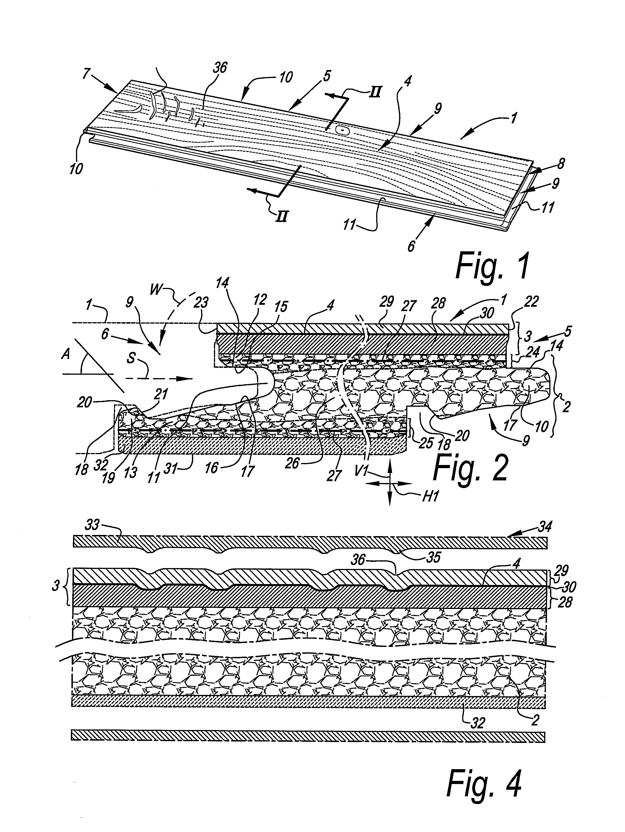
[0060]FIG. 1 represents a floor panel 1 for forming a floating floor covering.

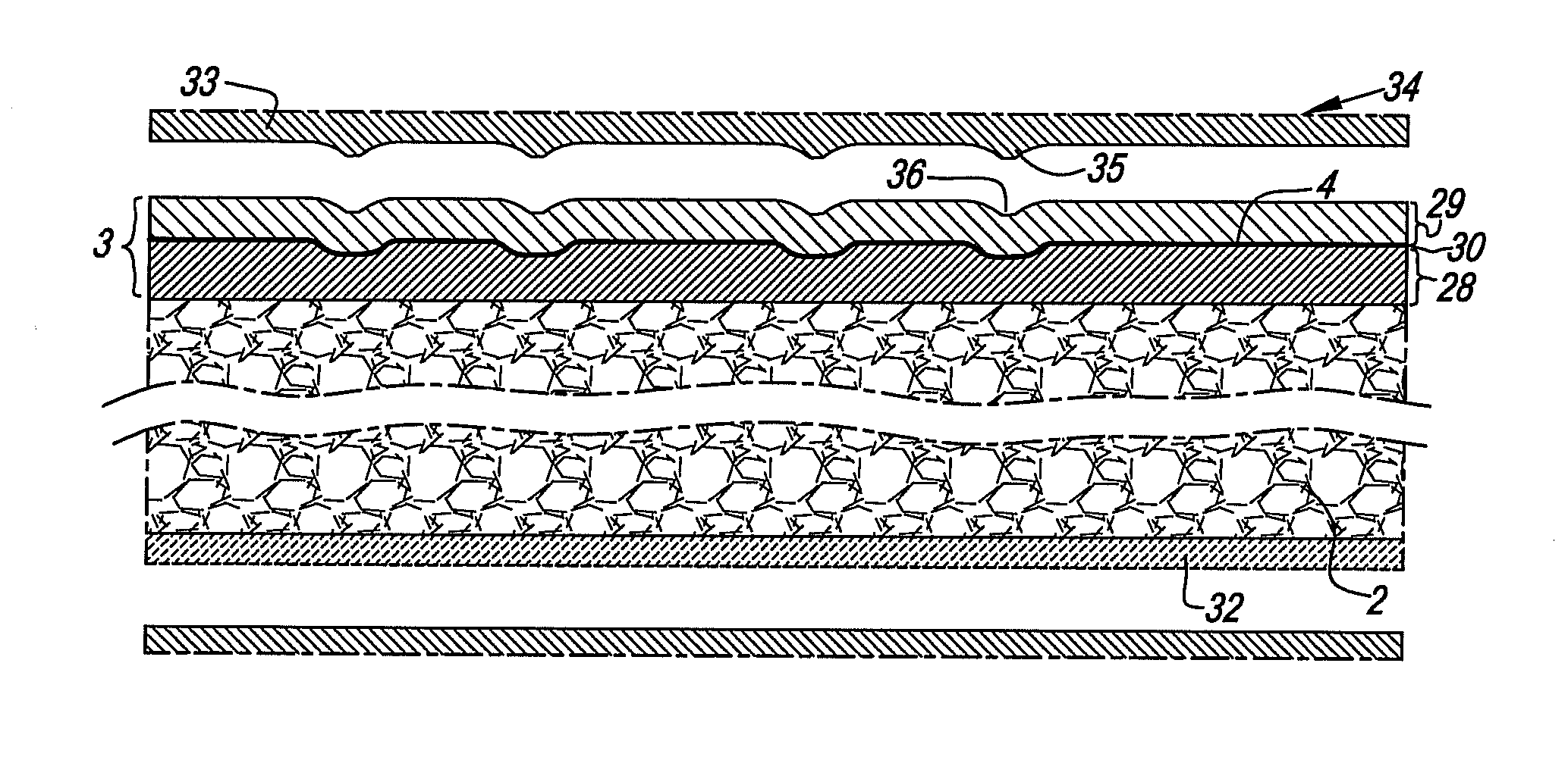
[0061]FIG. 2 clearly shows that the floor panel 1 is of the type which comprises at least a substrate 2 and a top layer 3 provided on this substrate 2, wherein the top layer 3 comprises a motif 4, in this case a wood motif.

[0062]In the example of FIGS. 1 and 2, this relates to a rectangular floor panel 1, which, at the first pair 5-6 as well as at the second pair 7-8 of opposite edges, is provided with mechanical coupling means 9.

[0063]FIG. 2 represents that the coupling means 9 at the first pair 5-6 of opposite edges, namely, the long edges of the floor panel 1, substantially are performed as a tongue 10, a groove 11, respectively. Herein, the groove 11 is flanked by an upper lip 12 and a lower lip 13. When two of such floor panels 1 are coupled to each other at these edges 5-6, the cooperation of the tongue 10 and the groove 11 as such leads to a locking in a vertical direction V1 perpendicular to the pl...


PUM

PropertyMeasurementUnit
thicknessaaaaaaaaaa
thicknessaaaaaaaaaa
thicknessaaaaaaaaaa

Abstract

In a method for manufacturing floor panels that have at least a substrate and a top layer provided on the substrate, the top layer including a thermoplastic layer that is translucent or transparent, the method may involve providing the top layer, including the thermoplastic layer, on the substrate. The method may also involve heating at least the thermoplastic layer, and structuring the thermoplastic layer using a mechanical press element.

Description

BACKGROUND OF THE INVENTION[0001]1. Field[0002]This invention relates to floor panels and methods for manufacturing floor panels.[0003]More particularly, the invention relates to floor panels of the type which is at least composed of a substrate and a top layer provided on this substrate, wherein said top layer comprises a motif. As known, above said motif a transparent or translucent synthetic material layer can be provided, which layer then forms part of said top layer.[0004]In particular, the present invention relates to floor panels of the type which, at two or more opposite edges, comprises coupling means or coupling parts, with which two of such floor panels can be coupled at the respective edges, such that they are locked together in a horizontal direction perpendicular to the respective edge and in the plane of the floor panels, as well as in a vertical direction perpendicular to the plane of the floor panels. Such floor panels can be applied for composing a so-called floati...

Claims


Application Information

Patent Timeline
Patent Type & Authority Applications(United States)
IPC IPC(8): E04F15/10B32B37/06B32B37/16B29C48/19B29C48/21
CPCY10T156/10B32B7/12B32B2309/04B32B21/02E04F15/18Y10T156/1039B32B2310/0825B44C1/24B32B37/06E04F15/10B29C47/065B32B2309/105Y10T156/1084B32B38/145B32B37/226B32B2309/12B32B37/153B44C5/04E04F15/107B32B2471/00B32B37/16B32B2309/02B32B2327/06B32B3/06B32B5/245B32B5/32B32B27/06B32B27/065B32B27/08B32B27/12B32B27/20B32B27/304B32B27/40B32B37/10E04F15/02038B32B2255/10B32B2266/0278B32B2266/0285B32B2266/0235B32B2264/102B32B2264/104B32B2262/101B32B2262/067B32B2307/734B32B2307/7265B32B2307/72B32B2307/718B32B2307/554B32B2307/546B32B2307/414B32B2307/412B32B2607/00B32B2479/00B32B2361/00B32B2375/00E04F15/02194E04F15/105B32B27/30B32B2266/08B32B2451/00B29C48/21E04F2201/0107E04F2201/023B32B5/145B32B5/18B32B2419/04E04F15/102B32B7/027B32B2255/26B32B2255/102B44C5/043B44C5/0476E04F15/02E04F15/02033E04F2201/0115E04F2201/0153E04F2201/049Y10T428/17Y10T428/195Y10T428/24488Y10T428/24777B32B7/02B29C65/72B29C48/19B29C66/45B29C65/56B29C48/175B29C65/7861B29C2793/0072B32B3/12
Inventor MEERSSEMAN, LAURENTSEGAERT, MARTINTHIERS, BERNARDCLEMENT, BENJAMINMAESEN, CHRISTOPHE
Owner FLOORING IND LTD
Why Eureka
Try Eureka