Glucose Sensor
- Summary
- Abstract
- Description
- Claims
- Application Information
AI Technical Summary
Benefits of technology
Problems solved by technology
Method used
Image
Examples
example
Example 1 and Reference Example 1
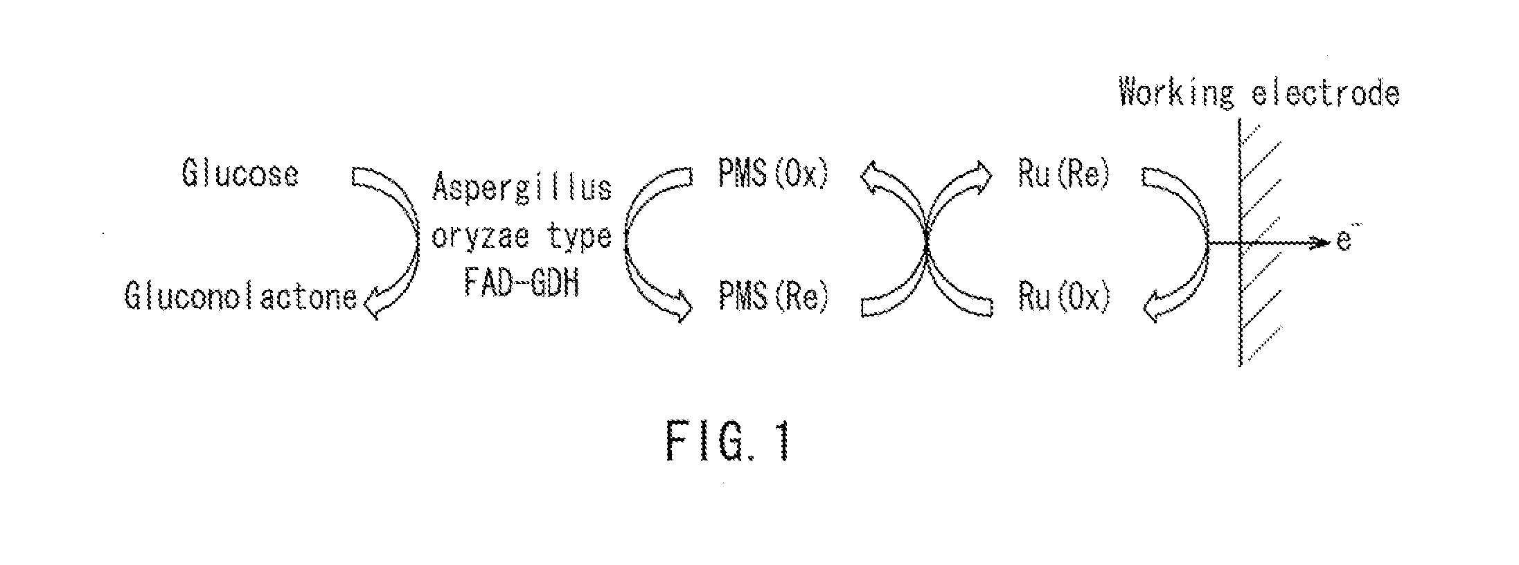
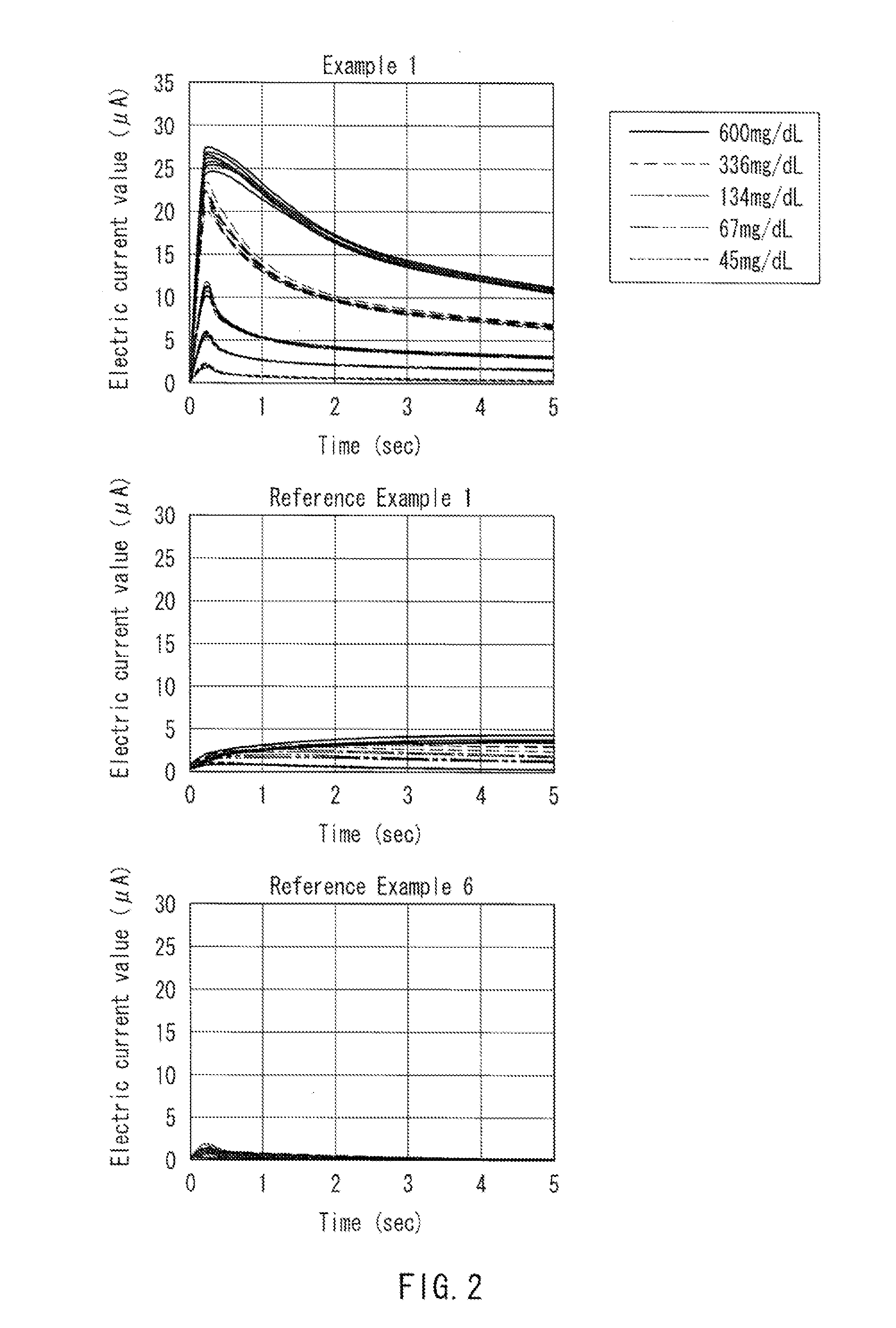
[0057]Glucose sensors of Example 1 and Reference Example 1 having the same structure as that shown in FIG. 3F were produced as described below.
[0058]First, a PET substrate (length: 50 mm, width: 6 mm, thickness: 250 μm) was prepared as the insulative substrate 11 for a glucose sensor, and a carbon electrode system composed of the working electrode 12 and the counter electrode 13 having lead parts, respectively, was formed on one surface of the insulative substrate 11 by screen printing.
[0059]Next, the insulative layer 14 was formed on the electrodes as described below. First, an insulative resin polyester was dissolved in solvent carbitol acetate so as to have a concentration of 75 wt %, whereby an insulative paste was prepared. This insulative paste was applied onto the electrodes by screen printing. The printing conditions were 300 mesh screen and a squeegee of pressure of 40 kg, and an amount of the paste to be printed, was set to 0.002 mL per 1 c...
example 2 and reference example 2
[0067]Glucose sensors of Example 2 and Reference Example 2 were produced in the same manner as that of Example 1 and Reference Example except that, in place of the Aspergillus oryzae type FAD-GDH of Example 1 and Reference Example 1 in which a sugar chain is bound to the non-glycosylated Aspergillus oryzae type FAD-GDH (manufactured by TOYOBO Co., Ltd.) in which the sugar chain is not added thereto is used.
[0068]Using the produced glucose sensors of Example 2 and Reference Example 2, time courses of electric current values were measured, which were measured after the reaction with body samples of venous whole blood having adjusted glucose concentrations, in the same manner as that of Example 1. As a result, it was found that, with the glucose sensors of Example 2, it was possible to measure glucose concentrations, since electric currents depending on glucose concentrations in the body samples were generated in the glucose sensors of Example 2 (data not shown). On the other hand, it ...
reference examples 3 to 7
[0069]Glucose sensors of Reference Examples 3 to 7 were produced in the same manner as that of Example 1 except that, in place of 1-methoxy PMS of Example 1, Cytochrome c from Sacharomyces cerevisiae (manufactured by Sigma-Aldrich Co. LLC), Cytochrome c from equine heart (manufactured by Sigma-Aldrich Co. LLC), and Cytochrome c from acetylated equine heart (manufactured by Sigma-Aldrich Co. LLC) were used, respectively. Glucose sensors of Reference Example 6 were produced in the same manner as that of Example 1 except that the ruthenium compound was excluded, and glucose sensors of Reference Example 7 were produced in the same manner as that of Example 1 except that the two types of mediators were not contained.
[0070]Using the produced glucose sensors of Reference Examples 3 to 5, time courses of electric current values were measured, which were measured alter the reaction with body samples of venous whole blood having adjusted glucose concentrations, in the same manner as that of E...
PUM
| Property | Measurement | Unit |
|---|---|---|
| Temperature | aaaaa | aaaaa |
| Mass | aaaaa | aaaaa |
| Substance count | aaaaa | aaaaa |
Abstract
Description
Claims
Application Information
 - R&D
- Intellectual Property
- Life Sciences
- Materials
- Tech Scout
- Unparalleled Data Quality
- Higher Quality Content
- 60% Fewer Hallucinations
Browse by: Latest US Patents, China's latest patents, Technical Efficacy Thesaurus, Application Domain, Technology Topic, Popular Technical Reports.
© 2025 PatSnap. All rights reserved.Legal|Privacy policy|Modern Slavery Act Transparency Statement|Sitemap|About US| Contact US: help@patsnap.com


