

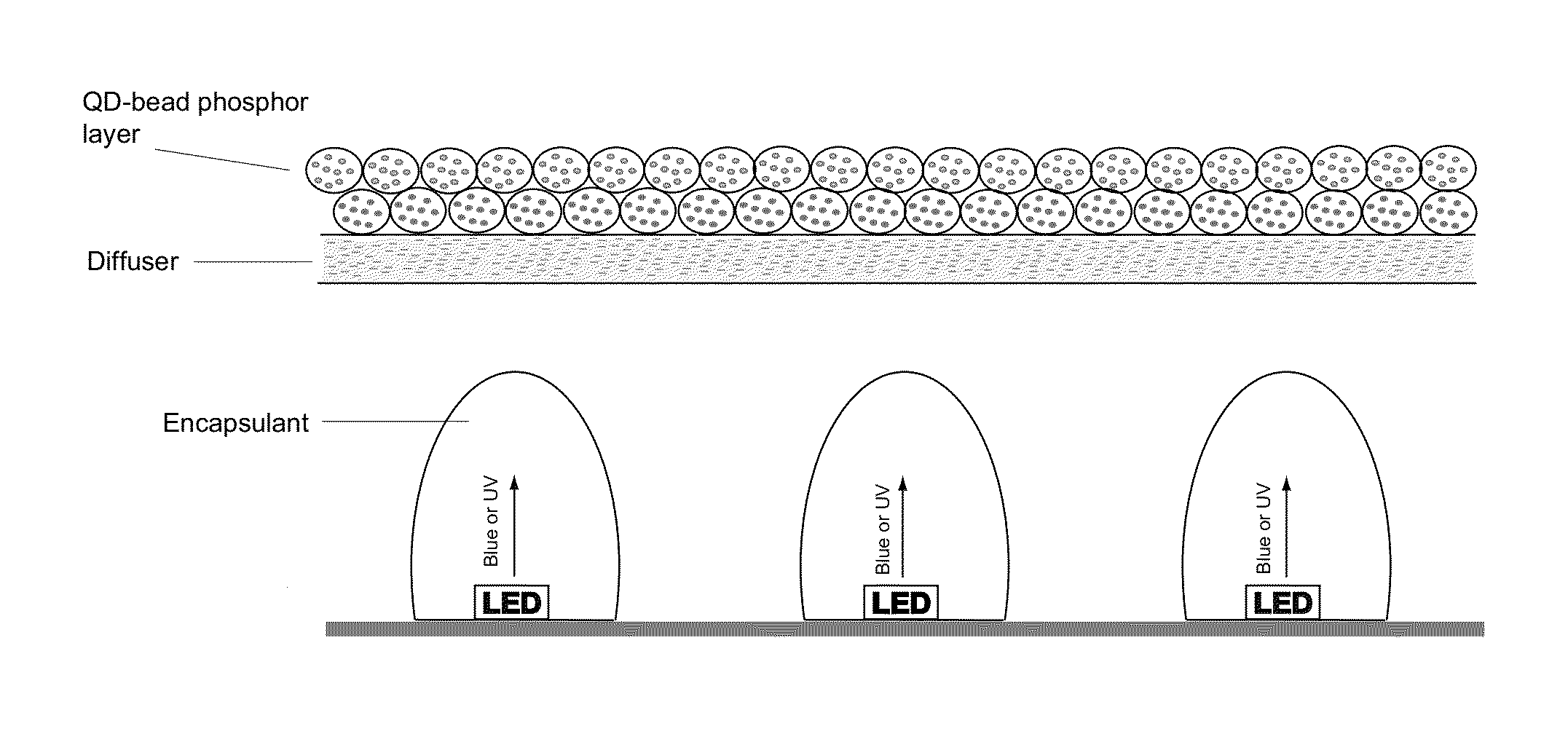
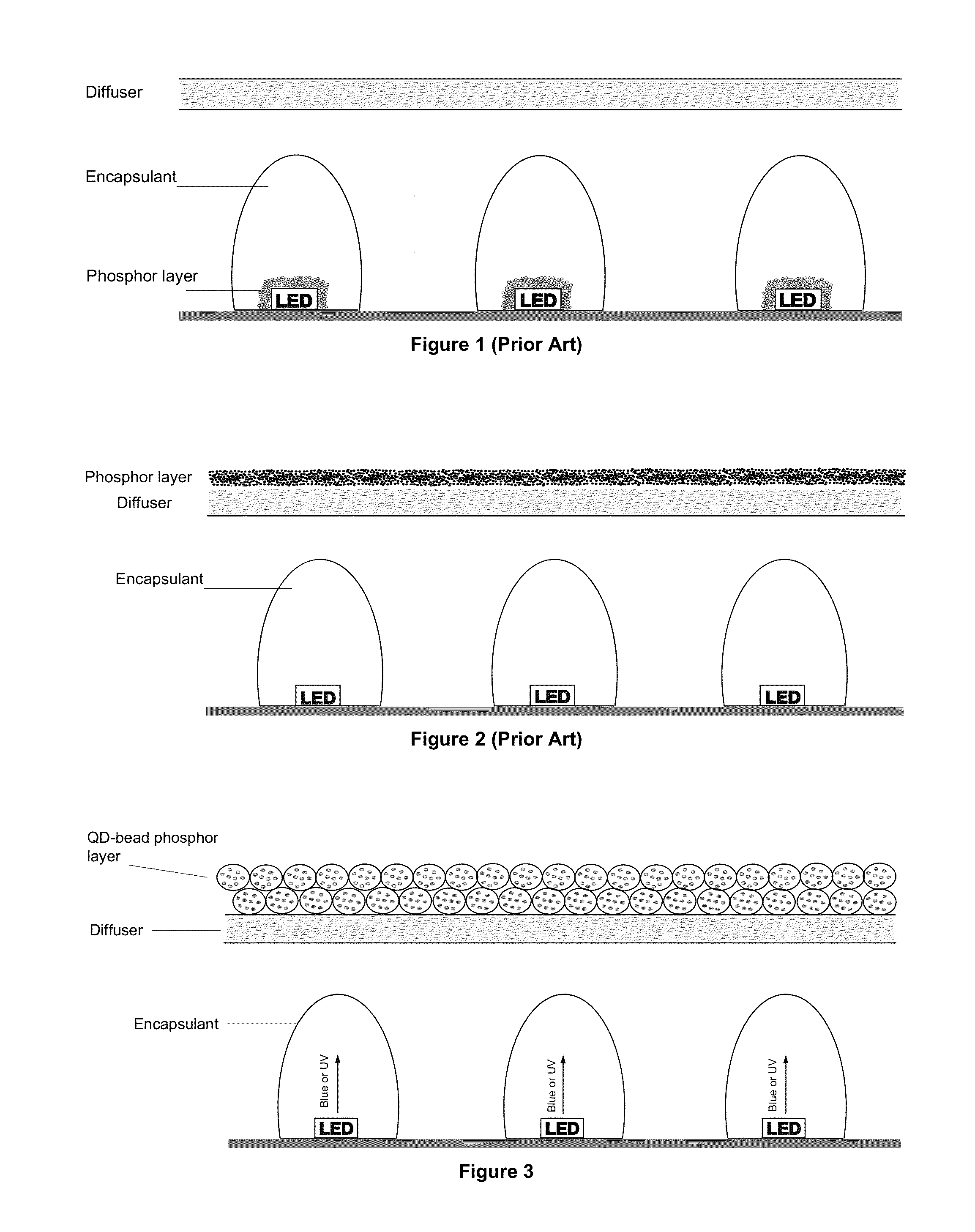
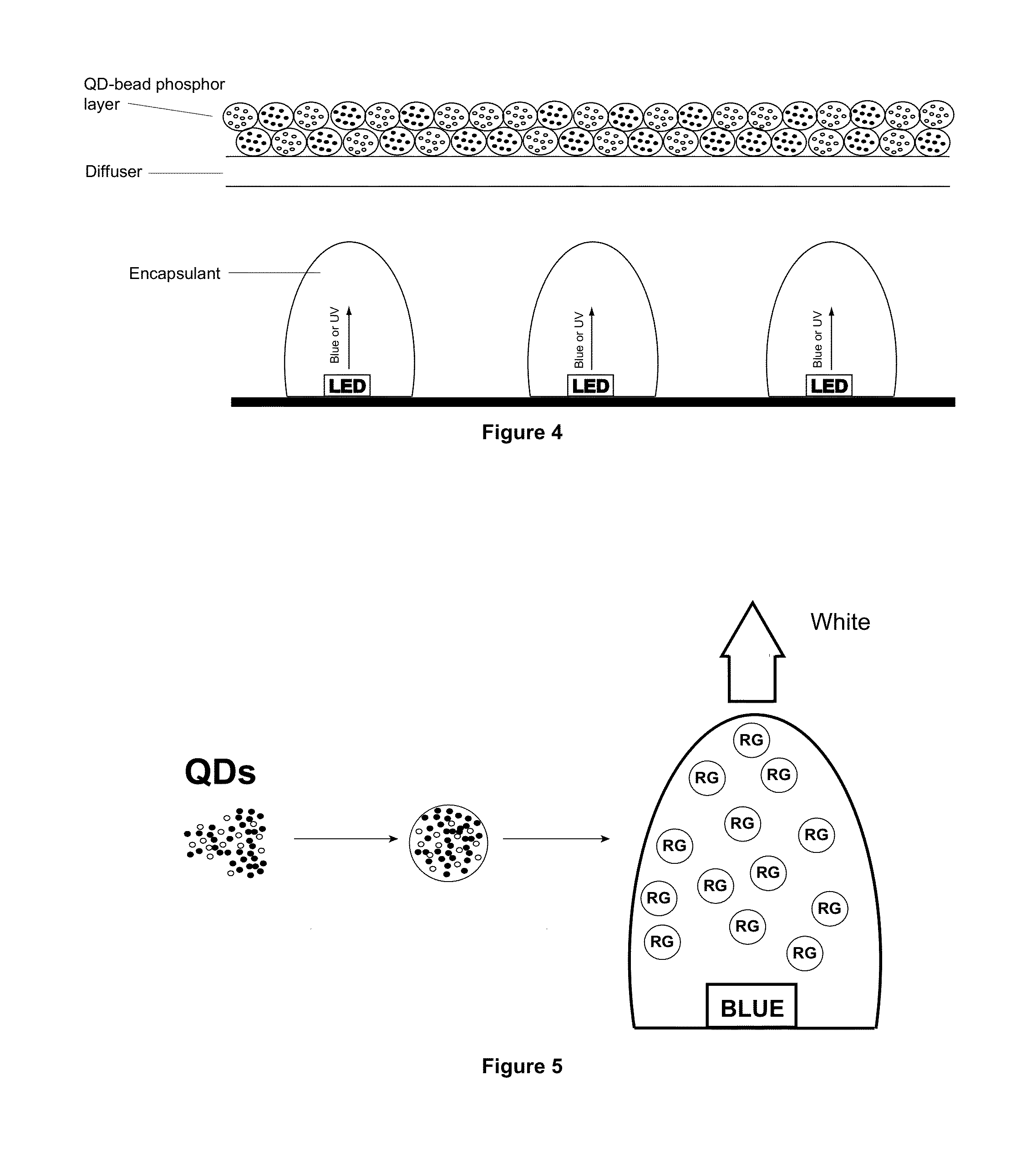
Semiconductor nanoparticle-based light emitting materials
a technology of semiconductor nanoparticles and light-emitting materials, applied in the direction of semiconductor devices, luminescent compositions, chemistry apparatuses and processes, etc., can solve the problems of poor colour control and colour rendering, poor colour control, and conventional led phosphor technology using down converting materials with poor colour rendering
- Summary
- Abstract
- Description
- Claims
- Application Information
AI Technical Summary
Benefits of technology
Problems solved by technology
Method used
Image

Examples
reference example 1
Preparation of CdSe / ZnS Core / Shell QDs
Preparation of CdSe Core QDs
[0126]Hexadecylamine (HDA, 500 g) was placed in a three-neck round bottomed flask and degassed by heating to 120° C. under a dynamic vacuum for >1 hour. The solution was then cooled to 60° C. and [HNEt3]4[Cd10Se4(SPh)16] (0.718 g, 0.20 mmols) was added through a side-port under a strong flow of nitrogen. TOPSe and Me2Cd.TOP (4 mmols each) were added dropwise into the reaction vessel, the temperature was increased to 110° C. and the reaction was allowed to stir for 2 hours after which time the solution was of a deep yellow colour. Further dropwise additions of equimolar amounts of TOPSe and Me2Cd.TOP were carried out while the temperature was progressively increased at a rate of 0.2° C. / min. In total 42 mmols of TOPSe and 42 mmols of Me2Cd.TOP were used. The reaction was stopped when the PL emission maximum had reached ˜600 nm, by cooling to 60° C. followed by addition of 300 mL of dry ethanol or acetone. This produced...
reference example 2
Preparation of InP / ZnS Core / Shell QDs
[0128]Preparation of InP Core QDs (400-800 nm emission)
[0129]Di-butyl ester (100 mL) and myristic acid (10.1 g) were placed in a three-neck flask and degassed at 70° C. under vacuum for one hour. After this period, nitrogen was introduced and the temperature increased to 90° C. ZnS molecular cluster [Et3NH]4[Zn10S4(SPh)16] (4.7 g) was added and the mixture allowed to stir for 45 minutes. The temperature was then increased to 100° C. followed by the dropwise addition of Indium myristate, In(MA)3 (1 M in ester, 15 mL) followed by (TMS)3P (1 M in ester, 15 mL). The reaction mixture was allowed to stir while increasing the temperature to 140° C. At 140° C., further dropwise additions of In(MA)3 (1 M, 35 mL) (left to stir for 5 min) and (TMS)3P (1 M, 35 mL) were made. The temperature was then slowly increased to 180° C. and further dropwise additions of In(MA)3 (1 M, 55 mL) followed by (TMS)3P (1 M, 40 mL) were made. By addition of the precursor in th...
reference example 3
Incorporation of QDs into Suspension Polymeric Beads
[0132]1% wt / vol polyvinyl acetate (PVA) aqueous solution was prepared by stirring for 12 hours followed by extensive degassing by bubbling nitrogen through the solution for a minimum of 1 hour. The monomers, methyl methacrylate and ethylene glycol dimethacrylate, were also degassed by nitrogen bubbling and used with no further purification. The initiator AIBN (0.012 g) was placed into the reaction vessel and put under three vacuum / nitrogen cycles to ensure no oxygen was present.
[0133]CdSe / ZnS core / shell QDs as prepared above were added to the reaction vessel as a solution in toluene and the solvent was removed under reduced pressure. Degassed methyl methacrylate (0.98 mL) was then added followed by degassed ethylene glycol dimethacrylate (0.15 mL). The mixture was then stirred at 800 rpm for 15 minutes to ensure complete dispersion of the QDs within the monomer mixture. The solution of 1% PVA (10 mL) was then added and the reaction...
PUM
| Property | Measurement | Unit |
|---|---|---|
| diameter | aaaaa | aaaaa |
| diameter | aaaaa | aaaaa |
| thick | aaaaa | aaaaa |
Abstract
Description
Claims
Application Information