

Production of solar cell modules
a solar cell and module technology, applied in the direction of photovoltaic energy generation, semiconductor devices, electrical equipment, etc., can solve the problems of reducing the usable fraction of incident light, affecting the performance of solar cells in long-term use, and affecting the performance of solar cells. , to achieve the effect of reducing the drop in solar cell performance in long-term use, excellent weather resistance, and maximum thermostability
Inactive Publication Date: 2013-04-11
EVONIK ROEHM GMBH
View PDF1 Cites 3 Cited by
- Summary
- Abstract
- Description
- Claims
- Application Information
AI Technical Summary
Benefits of technology
The present invention aims to find a solution to reduce the performance drop of solar cells in long-term outdoor use, especially at high temperature and / or high humidity. The focus is on achieving excellent resistance to weathering, maximum thermostability, and maximum transparency with minimum water absorption. Materials are needed that offer optimum protection of solar modules and make optimum efficiency possible, while also minimizing corrosive substance release and maximizing adhesion to the various components of a solar cell module.
Problems solved by technology
The photovoltaic cell cannot withstand extreme external conditions, because it corrodes easily and is very fragile.
However, light-induced and / or heat-induced degradation of the reinforcing agent and consequent yellowing of the reinforcing agent and / or peeling of the photovoltaic cell are often observed, when the module is used outside for a long time, e.g. ten years.
The yellowing of the reinforcing agent leads to a decrease in the usable fraction of the incident light and therefore lower electrical performance.
Furthermore, peeling of the photovoltaic cell permits penetration of moisture, which can lead to corrosion of the photovoltaic cell itself or of metallic parts in the solar cell module and may also result in impairment of the performance of the solar cell module.
Although the EVAs usually employed are good reinforcing agents in themselves, they are gradually degraded by hydrolysis and / or pyrolysis.
This leads to yellowing of the reinforcing agent, to a decrease in mechanical strength and to a decrease in adhesiveness of the reinforcing agent.
In addition, the acetic acid released acts as a catalyst and causes additional acceleration of degradation.
Furthermore, there is the problem that the photovoltaic cell and / or other metal parts in the solar cell module are corroded by the acetic acid.
However, both the resistance to weathering and the efficiency of such solar cell modules are limited.
However, that publication does not give any information on the use of the mouldings for the production of solar cell modules.
However, that publication does not give any information on the use of the composition for the production of solar cell modules.
However, that publication does not give any information on the use of the mouldings for the production of solar cell modules.
Method used
View moreImage
Smart ImageViewing Examples

Examples
example 1
® 7H with 0.04 wt. % Tinuvin® 312
example 2
® 7H with 0.06 wt. % Tinuvin® 312
example 3
® 7H with 0.08 wt. % Tinuvin® 312
Login to View More PUM
 Abstract
The invention relates to the use of a) at least one (poly)alkyl(meth)acrylate and b) at least one compound according to formula (I), wherein the radicals R1 and R2 independently represent an alkyl or cycloalkyl radical having 1 to 20 carbon atoms, for producing solar cell modules, in particular for producing light concentrators for solar cell modules.
Description
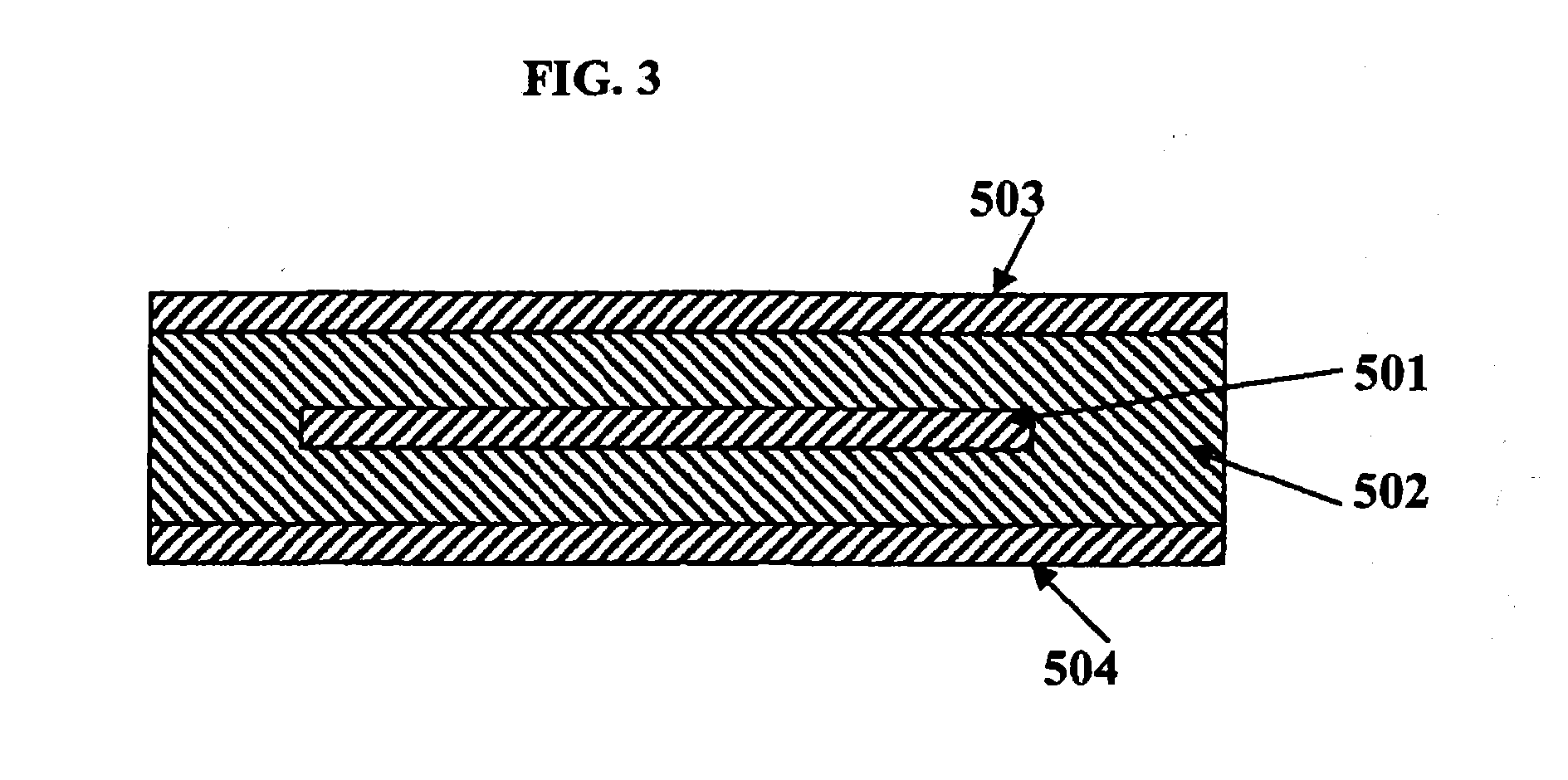
[0001]The present invention relates to the production of solar cell modules and the corresponding solar cell modules.PRIOR ART[0002]A solar cell or photovoltaic cell is an electrical component, which converts the radiant energy contained in light, in particular in sunlight, directly into electrical energy. The physical basis of this conversion is the photovoltaic effect, which is a special case of the internal photoelectric effect.[0003]FIG. 3 is a schematic cross-section showing the basic structure of a solar cell module. In FIG. 3, 501 denotes a photovoltaic cell, 502a reinforcing agent, 503a plate and 504a rear wall. Sunlight impinges on the light-sensitive surface of the photovoltaic cell 501, having passed through the plate 503 and the reinforcing agent 502, and is converted into electrical energy. The current produced is delivered by output terminals (not shown).[0004]The photovoltaic cell cannot withstand extreme external conditions, because it corrodes easily and is very fra...
Claims
Login to View More Application Information
Patent Timeline
 IPC IPC(8): H01L31/0203H01L31/18
CPCC08L33/12H01L31/0203C08K5/20Y02E10/52H01L31/18H01L31/0481H01L31/0543H01L31/048C08L33/06H01L31/0488
InventorBATTENHAUSEN, PETERBECKER, ERNSTSCHULTES, KLAUSSTROHKARK, SVEN
OwnerEVONIK ROEHM GMBH