Methods for manufacturing molecular arrays

a manufacturing method and molecular array technology, applied in the field of molecular array manufacturing, can solve the problems of large variability in the quality of synthesized peptides, high cost of generating arrays with tens of thousands or more spotted peptides, and inefficient direct fabrication process,

Active Publication Date: 2013-05-02
PROGNOSYS BIOSCI
View PDF4 Cites 114 Cited by
  • Summary
  • Abstract
  • Description
  • Claims
  • Application Information

AI Technical Summary

Problems solved by technology
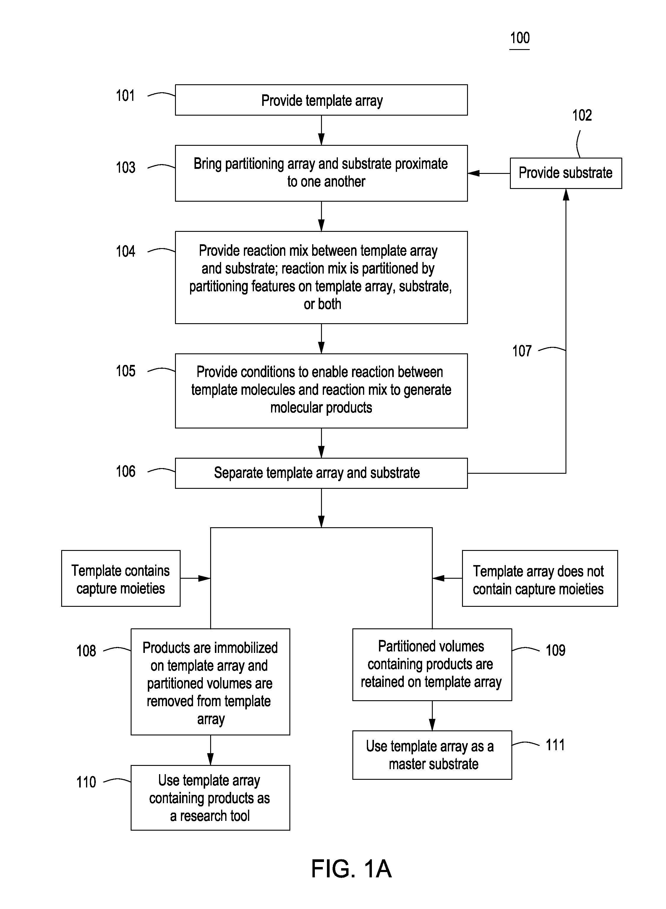
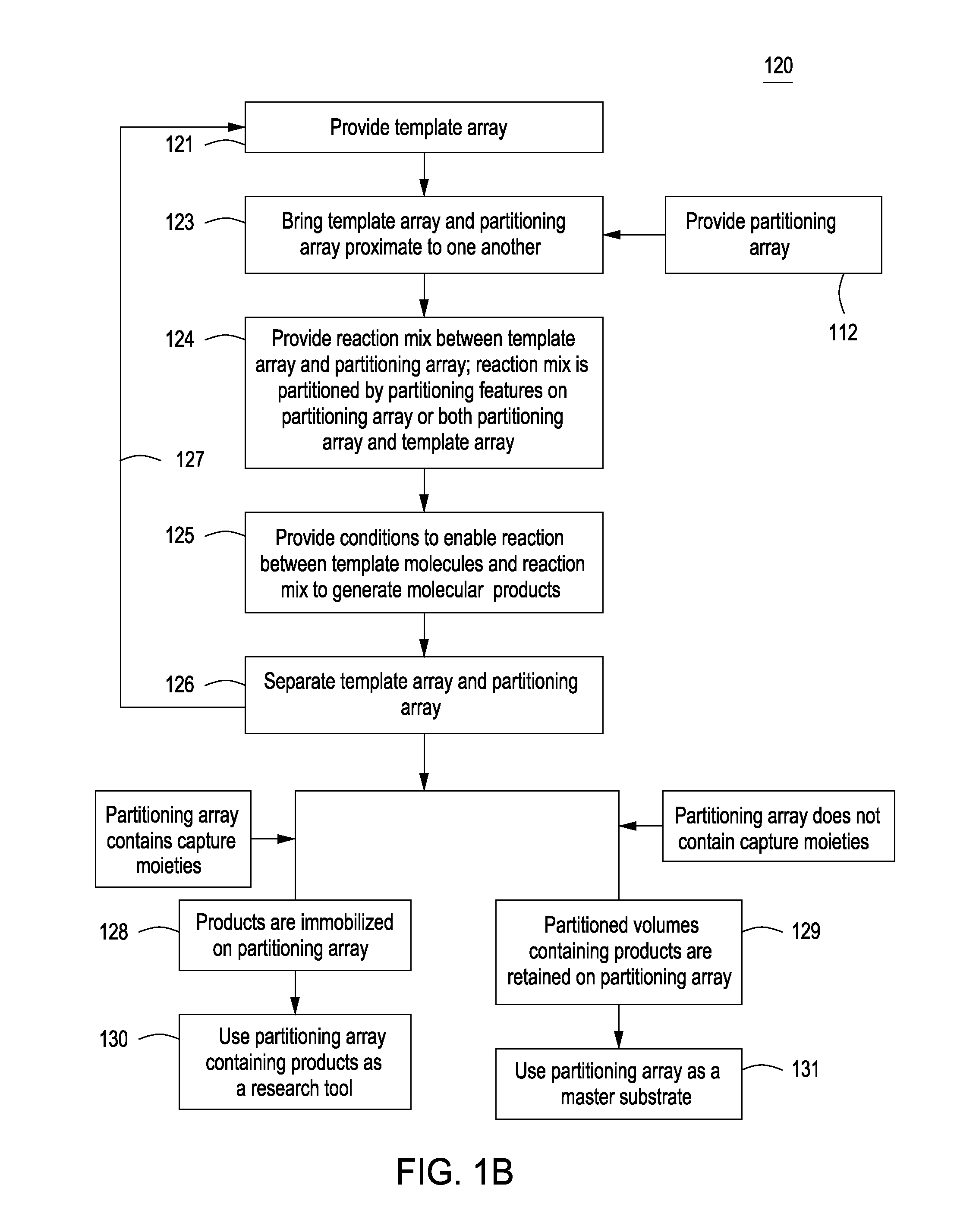
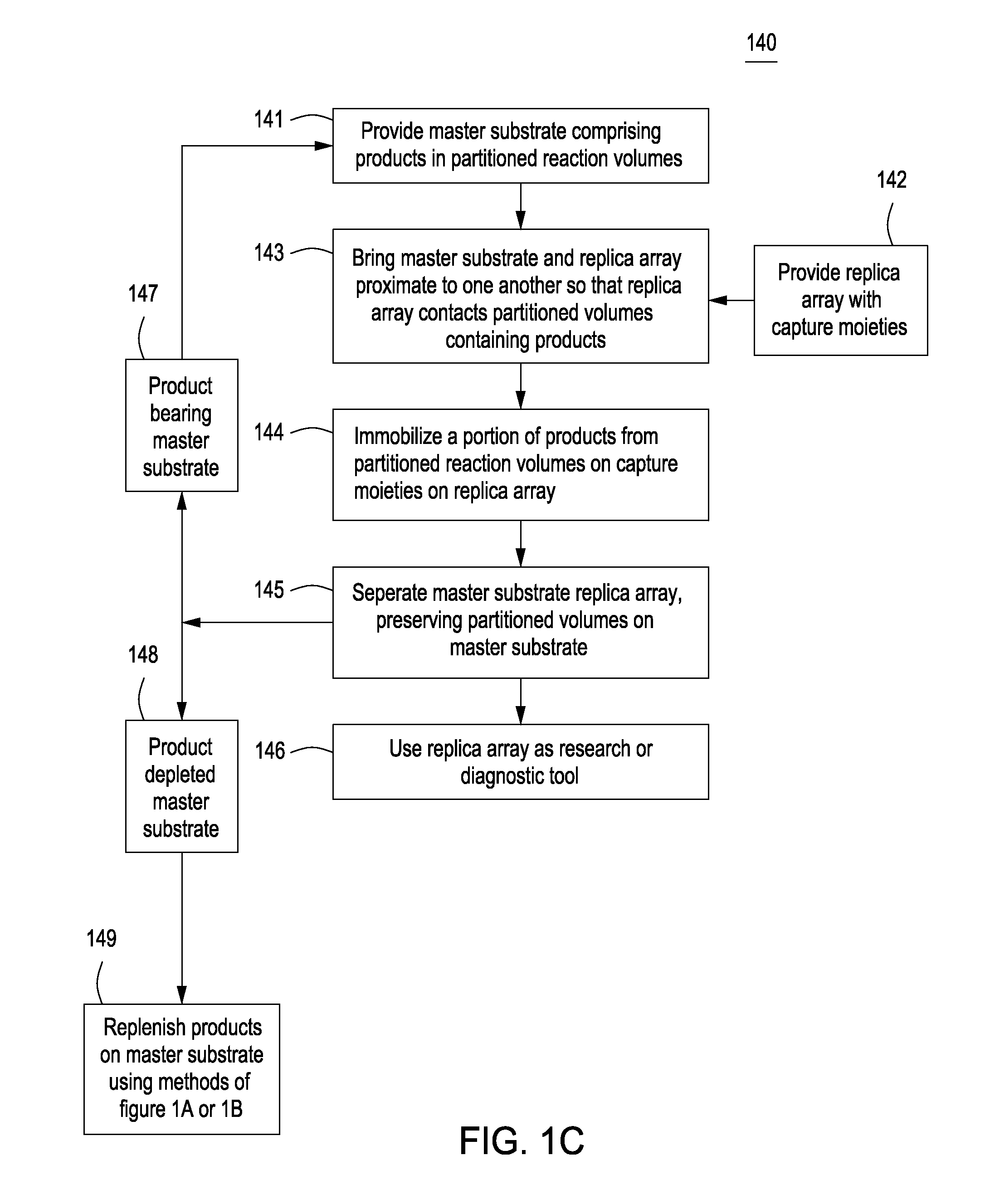
However, the cost of generating arrays with tens of thousands or more spotted peptides would be astronomically high.
Several methods enable direct chemical synthesis of peptides in microarray format, which reduces costs, but these methods still have the major drawback of variability in the quality of the synthesized peptides (Antohe and Cooley, Methods Mol. Biol., 381:299-312 (2007)).
Moreover, the direct fabrication process can be very slow and inefficient (Hilpert, et al., Nat. Protoc., 2:1333-49 (2007)).
These approaches utilize individually-synthesized nucleic acid templates rather than individually-synthesized peptides; however, the cost of the nucleic acid templates is often higher than the cost of individual peptides arrayed by traditional methods.
Further, diffusion of the peptide products limits the feature density of these types of arrays.

Method used


Image

  • Methods for manufacturing molecular arrays
  • Methods for manufacturing molecular arrays
  • Methods for manufacturing molecular arrays

Examples


example 1

Partitioning Array Fabrication

[0134]A partitioning array was fabricated from a standard silicon wafer. First, a patterned gasket comprising a boundary region surrounding the area to contain partitioning features was formed on the wafer by using UV lithography to pattern a 20 μm-thick layer of SU-8 epoxy-based negative photoresist on the wafer. The gasket was formed such that the partitioning array, when brought into proximity with another substrate (a dummy substrate, template array or capture substrate or replica array, for example), would form a flowcell. The wafer was then baked at 300° C. to make the SU-8 substantially impervious to subsequent processing. The wafer was then cryo-etched using reactive-ion etching with inductively coupled plasma (RIE / ICP) at negative 140° C. using SF6 and O2 to form black silicon. The black silicon consisted of conical pillars, approximately 2 μm high and 100-200 nm wide.

[0135]A conformal layer of silicon dioxide approximately 50-200 nm in thickne...

example 2

Capture Substrate Fabrication

[0136]A borofloat glass microscope slide was used to prepare the capture substrate. First, the slide was cleaned using solvents and a strong acid / oxidizer bath, and were then cleaned further using a UV-Ozone cleaner (Jelight, Inc., Irvine, Calif.). The slides were functionalized using (3-aminopropyl)trimethozysilane (APTMS) in a vapor deposition system at 150° C. and 3 torr for 10 minutes. Amine functionality on the capture substrate (chip) was confirmed by labeling with Lissamine Rhomdamine B Sulfonyl Chloride, an amine-reactive fluorescent dye, and imaging with a microarray scanner.

example 3

Capture Substrate Printing

[0137]The flowcell was assembled by bringing the silicon partitioning array into contact with the capture substrate so that the SU-8 gasket surrounding the region of partitioning features contacted the edges of the capture substrate and the black silicon surface of the partitioning array was held at a distance equal to the thickness of the gasket. The partitioning array and capture substrate were then clamped together, and a tube was connected to the output port of the flowcell, where the output port was formed by one of the holes drilled into the partitioning array. The tube was then connected to a vacuum source.

[0138]A small volume of buffer containing reactive molecules, in this case fluorescein isothiocyanate (FITC), was pipetted into the input port formed by the second hole drilled into the partitioning array, where the FITC was pulled through the flow cell by the vacuum. The entire volume of the flow-cell was filled temporarily while the buffer transi...


PUM

PropertyMeasurementUnit
volumesaaaaaaaaaa
melting temperatureaaaaaaaaaa
sizeaaaaaaaaaa

Abstract

The methods of the present invention provide methods for manufacturing a master substrate and methods for manufacturing replica arrays from the master substrate. The methods may be used, for example, directly to manufacture or “print” peptide arrays from a DNA array; however, the methods are applicable to a wide range of manufacturing applications for use any time multiple copies of an array needs to be printed.

Description

[0001]This invention was made with the support of the Federal Government under Grant No. R44RR025296. The Federal Government has certain rights in this invention.FIELD OF THE INVENTION[0002]This invention relates to methods for manufacturing molecular arrays.BACKGROUND OF THE INVENTION[0003]In the following discussion certain articles and methods may be described for background and introductory purposes. Nothing contained herein is to be construed as an “admission” of prior art. Applicant expressly reserves the right to demonstrate, where appropriate, that the articles and methods referenced herein do not constitute prior art under the applicable statutory provisions.[0004]Molecular arrays typically are precisely-ordered arrangements of large sets of nucleic acid, protein or other molecules immobilized on solid substrates, and are valuable tools in areas of research that require the identification and / or quantification of many molecules in parallel. DNA arrays are the most common ty...

Claims


Application Information

Patent Timeline
Patent Type & Authority Applications(United States)
IPC IPC(8): C40B40/10C40B50/06
CPCC40B50/06B01J19/0046B01J2219/00317B01J2219/00382B01J2219/00585B01J2219/00619B01J2219/00722C12Q1/6837B01J2219/00725C40B40/06C40B60/12C40B50/18C12Q2565/515
Inventor ROUTENBERG, DAVID A.
Owner PROGNOSYS BIOSCI
Why Eureka
Try Eureka