
Purification of Carbon Dioxide

a carbon dioxide and purification technology, applied in the direction of liquefaction, separation processes, lighting and heating apparatus, etc., can solve the problems of reducing the reducing the power available for export, and not providing further details of how heat integration might be achieved, so as to achieve the effect of reducing the power consumption of the combined system, reducing the power consumption of the cpu, and reducing the power consumption

Inactive Publication Date: 2013-05-09
AIR PROD & CHEM INC
View PDF8 Cites 14 Cited by
  • Summary
  • Abstract
  • Description
  • Claims
  • Application Information

AI Technical Summary

Benefits of technology

The present invention provides methods for purifying crude carbon dioxide gas and generating power using an oxyfuel combustion process with CO2 capture, with a significantly reduced total parasitic power consumption as compared to existing methods. The invention achieves this by partially providing the refrigeration duty for cooling the feed to the plant using evaporated liquid refrigerant and heated independent refrigerant fluid, as well as integrating the CPU and ASU to further reduce power consumption. These methods offer improved energy efficiency and reduced carbon dioxide emissions, making them useful in industrial applications such as power generation.

Problems solved by technology

However, using pure oxygen for the combustion would result is a very high combustion temperature which would not be practical in a furnace or boiler.
In an oxyfuel power plant with CO2 capture, both the ASU and CPU consume power and reduce the power available for export.
However, no further details of how the heat integration might be achieved are provided.

Method used


Image

  • Purification of Carbon Dioxide
  • Purification of Carbon Dioxide
  • Purification of Carbon Dioxide

Examples


example 1

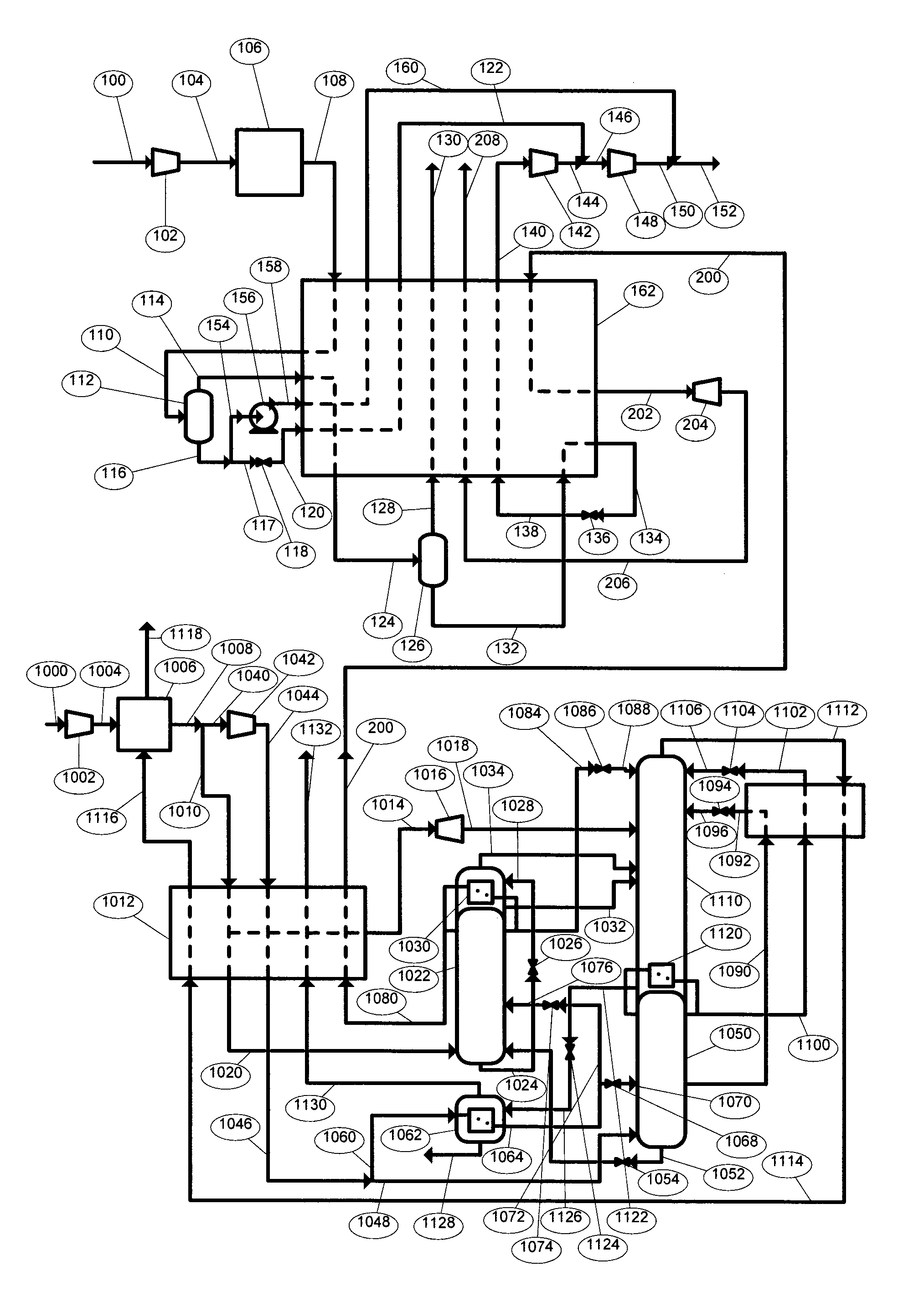
[0120]Similar computer simulations have been carried out to calculate key heat and mass balance and power consumption data for the integrated system depicted in FIG. 2b. The simulations were again based on an oxyfuel coal fired power station with a nominal net output of 500 MW.

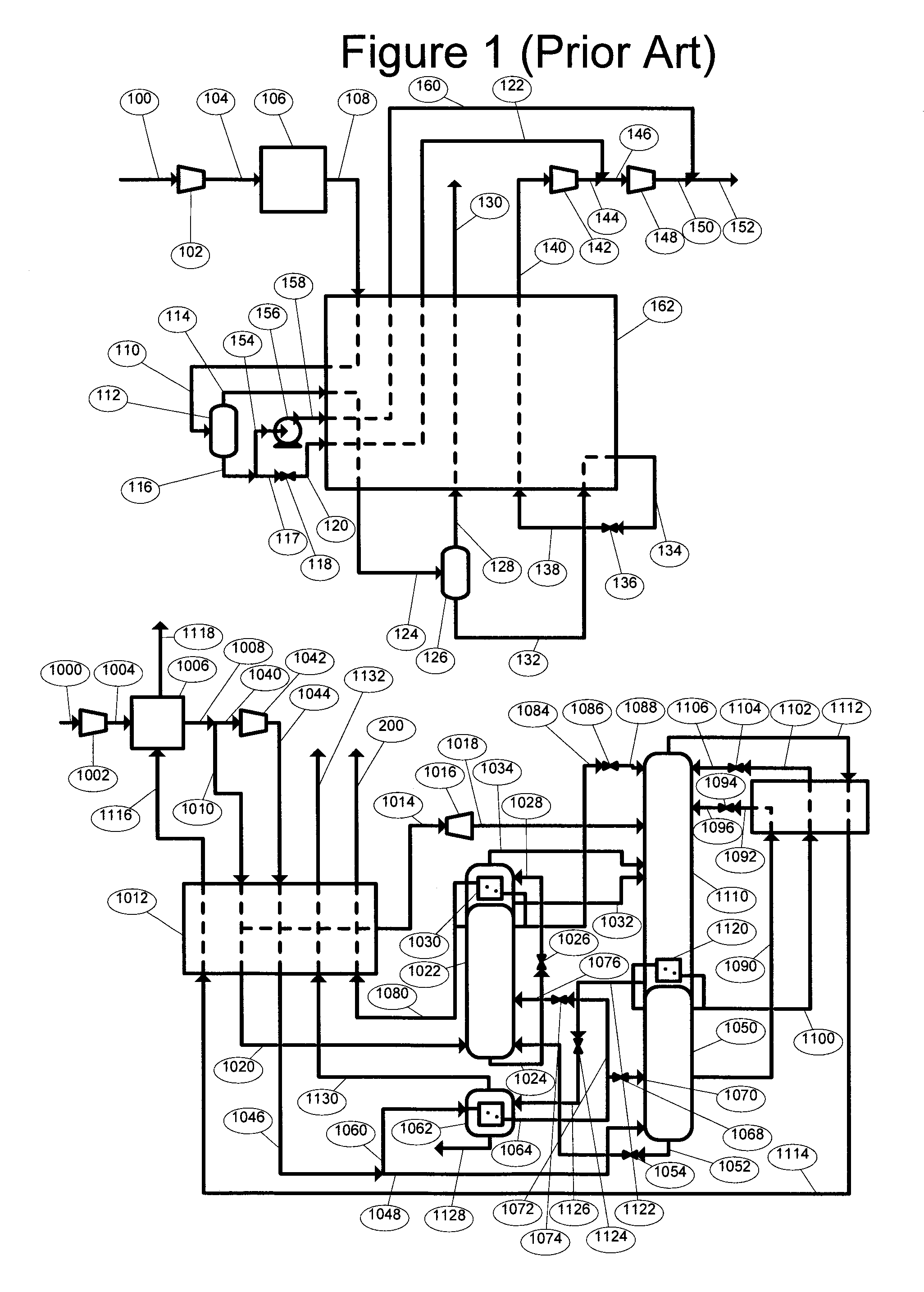
[0121]As indicated in Table 3, the total ASU and CPU power consumption for this arrangement is 132540 kW which represents a significant reduction of 1.4% in total consumption over the prior art process of FIG. 1. This example demonstrates that efficiency of the ASU process is increased by withdrawing pressurised nitrogen from the ASU, and this more than offsets the lower efficiency of the refrigeration system in the CPU.

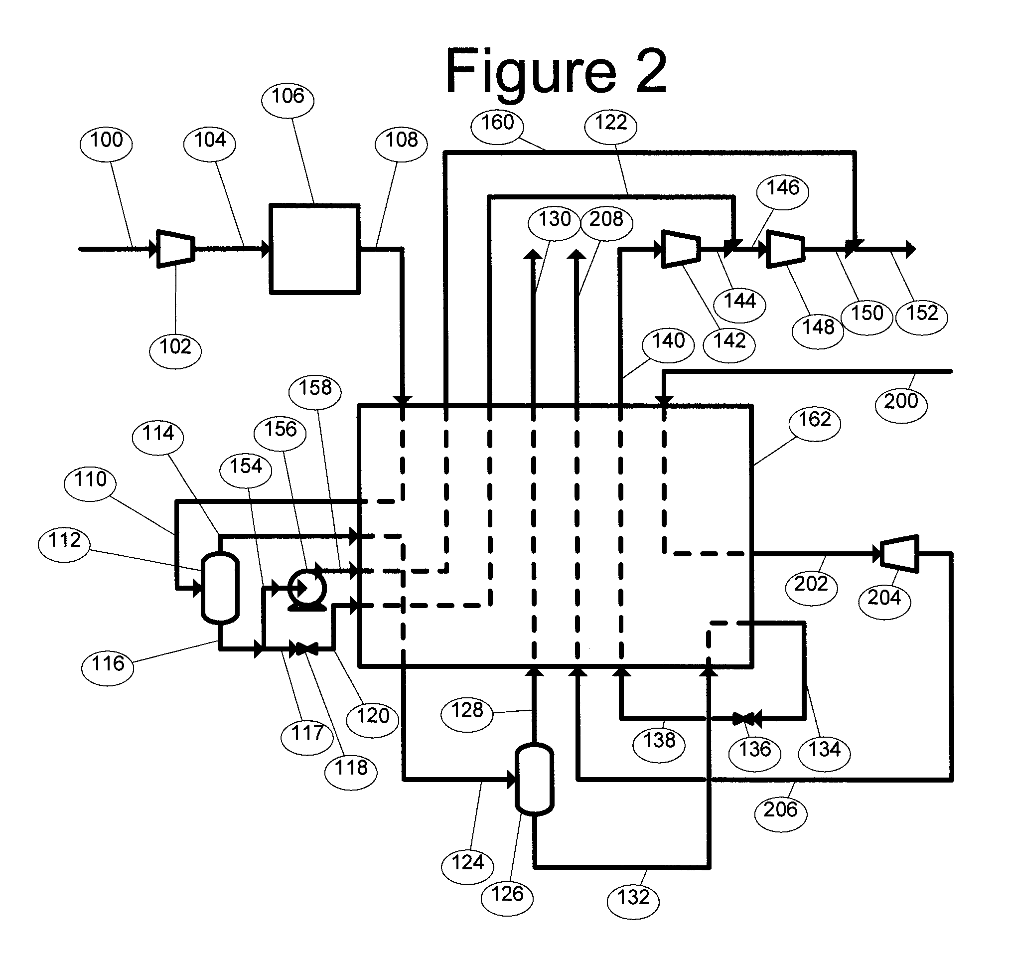
TABLE 3CPU line No.108110122124130140150152160200202208Temper-° C.20.0−37.111.7−53.511.711.720.018.211.76.8−20.511.7aturePressureBar30.0 (3)29.9 (3)18.4 (2)29.8 (3)29.7 (3)13.1 (1)110.0 (11)110.0 (11)110.0 (11)2.6 (0.3)2.5 (0.3)1.0 (0.1)(MPa)Molarkmol / s4.0584.0581.8341.5981.1710.4272.2612.8870....


PUM

PropertyMeasurementUnit
temperatureaaaaaaaaaa
pressureaaaaaaaaaa

Abstract

Refrigeration duty in a carbon dioxide purification unit (CPU) operating at elevated pressure and sub-ambient temperature can be provided in at least a first part by indirect heat exchange against at least latent heat of at least one liquid first refrigerant, preferably carbon dioxide liquid(s) produced in the CPU, thereby typically evaporating the liquid(s), and a second part by indirect heat exchange with sensible heat energy alone of a second refrigerant. The second refrigerant may be nitrogen gas imported from an integrated cryogenic air separation unit (ASU) or carbon dioxide liquid exported from the CPU, cooled and returned to the CPU. One advantage is that total power consumption of the CPU and an integrated ASU is reduced.

Description

BACKGROUND OF THE INVENTION[0001]The present invention relates to a method of purifying crude carbon dioxide gas using a low temperature carbon dioxide purification process. Specifically, the present invention resides in the manner in which the refrigeration duty for such a method may be provided in order to reduce overall energy consumption. The present invention has particular application in processes that capture carbon dioxide from flue gas produced in an oxyfuel combustion process to raise steam for electric power generation, in which oxygen for the combustion is produced in a cryogenic air separation unit (ASU).[0002]It has been asserted that one of the main causes of global warming is the rise in greenhouse gas contamination in the atmosphere due to anthropological effects. The main greenhouse gas which is being emitted, carbon dioxide (CO2), has risen in concentration in the atmosphere from 270 ppm before the industrial revolution to the current figure of about 378 ppm. Furt...

Claims


Application Information

Patent Timeline
Patent Type & Authority Applications(United States)
IPC IPC(8): F25J3/08C01B32/50
CPCB01D53/002B01D2257/504F25J3/04206F25J3/04303F25J3/04309F25J3/04393F25J3/04412F25J3/04448F25J3/04533F25J3/04563F25J3/04612F25J2210/42F25J2210/70F25J2210/80F25J2215/04F25J2220/82F25J2235/80F25J2240/12F25J2260/02F25J2260/44F25J2260/80F25J2270/14F25J2270/16F25J2270/42F25J2270/904Y02C10/12F25J3/067F25J2290/34F25J2270/02Y02C20/40
Inventor HIGGINBOTHAM, PAUL
Owner AIR PROD & CHEM INC
Learn More