Automatic range corrected flash ladar camera

a range correction and flash ladar technology, applied in the field of remote sensing of objects and the application of lasers, can solve the problems of inability to accurately predict the delay of a trigger pulse, modal stability, and complicated time of arrival determination, so as to improve reliability, repeatability, and thermal stability. the effect of stability

Active Publication Date: 2013-05-23
CONTINENTAL AUTONOMOUS MOBILITY US LLC
View PDF16 Cites 43 Cited by
  • Summary
  • Abstract
  • Description
  • Claims
  • Application Information

AI Technical Summary

Benefits of technology

[0010]The present invention comprises a flash ladar camera system with an optimized laser transmitter adapted to improve laser pulse shape and repeatability, reduce pulse timing jitter, and provide an amplitude corrected transmit timing reference. Addi...

Problems solved by technology

The infrared focal plane array detector and readout integrated circuit input amplifier together exhibit a time delay which varies with input signal amplitude, complicating the time of arrival determination for any reflected light energy.
Performance limitations of solid state lasers employing thes...

Method used


Image

  • Automatic range corrected flash ladar camera
  • Automatic range corrected flash ladar camera
  • Automatic range corrected flash ladar camera

Examples


Embodiment Construction

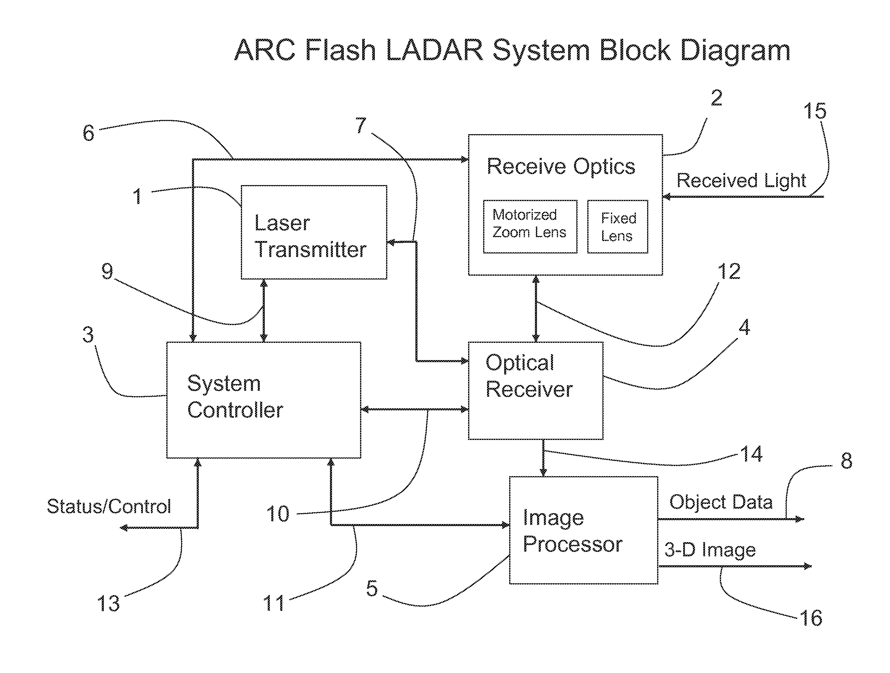
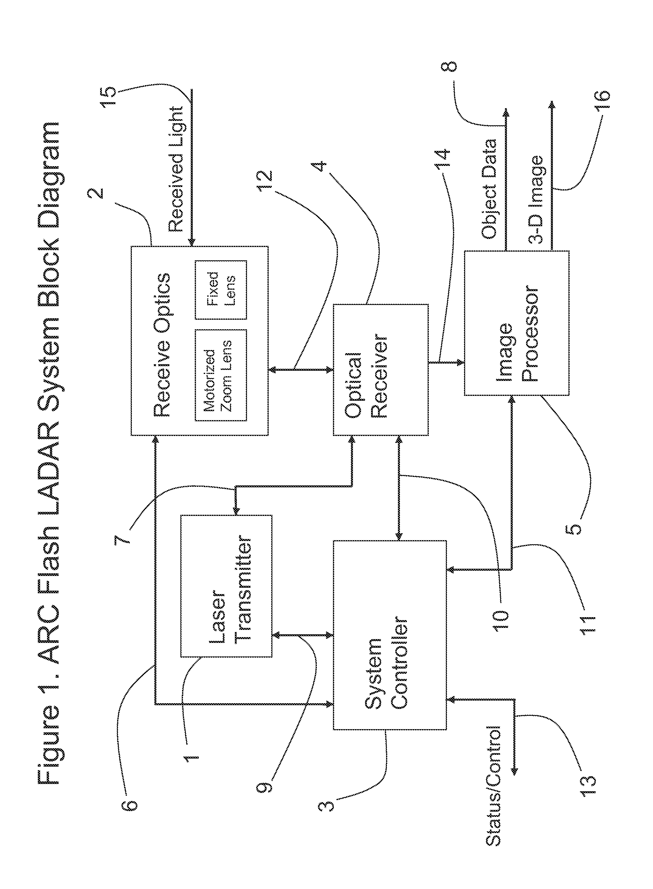
[0025]A preferred embodiment of the present invention, the Automatic Range Corrected (ARC) Flash Ladar is depicted in block diagram form in FIG. 1. The system is designed to produce a 3-dimensional image using a pulsed laser transmitter, an infrared focal plane array detector, and timing circuits associated with each pixel of the array detector. The ARC Flash Ladar is capable of producing range and intensity data for any object or scene within its field of view from a single pulse of Laser Transmitter 1, in conjunction with System Controller 3, and Infrared Optical Receiver 4. An optional Image Processor 5 produces object data and enhanced 3-D images. Receive Optics 2 are interchangeable conventional telescopic lenses adapted to a specific range and field of view and serve in the same manner as in an ordinary 2D still or motion camera. The shorthand terms “flash laser radar”, and “flash ladar” may be used interchangeably herein to refer to Laser Transmitter 1, Receive Optics 2, Syst...


PUM


Abstract

A three dimensional imaging camera comprises a system controller, pulsed laser transmitter, receiving optics, an infrared focal plane array light detector, and an image processor. The described invention is capable of developing a complete 3-D scene from a single point of view. The 3-D imaging camera utilizes a pulsed laser transmitter capable of illuminating an entire scene with a single high power flash of light. The 3-D imaging camera employs a system controller to trigger a pulse of high intensity light from the pulsed laser transmitter, and counts the time from the start of the transmitter light pulse. The light reflected from the illuminated scene impinges on a receiving optics and is detected by a focal plane array optical detector. An image processor applies image enhancing algorithms to improve the image quality and develop object data for subjects in the field of view of the flash ladar imaging camera.

Description

RELATED APPLICATIONS[0001]This application claims priority to U.S. Provisional Application No. 61 / 535,113 filed Sep. 15, 2011 which is incorporated herein by reference. Additionally, the subject matter disclosed in U.S. Pat. Nos. 5,696,577, 6,133,989, 5,629,524, 6,414,746, 6,362,482, and U.S. Patent Application Publication No. 2002 / 0117340 are incorporated herein by reference.BACKGROUND[0002]Conventional 2-D cameras for capturing visible images rely on rectangular arrays of pixellated light sensitive Charge Coupled Devices (CCDs) or CMOS sensors. These sensors are generically referred to as focal plane arrays. They are positioned directly behind an imaging lens system in the focal plane of the lens. Similarly, the laser radar described herein relies on the performance of a focal plane array detector. The detector in this case must respond to wavelengths outside of the visible range, in the near infrared spectrum. The detector material is a binary compound of Indium Phosphide (InP), ...

Claims


Application Information

Patent Timeline
IPC IPC(8): G01S17/06G01S17/931G01S17/89
CPCG01S17/06G01S17/936G01S7/4814G01S7/4816G01S7/4818G01S7/484H01S3/0627H01S3/08063H01S3/09408H01S3/094084H01S3/0941H01S3/09415H01S3/10092H01S3/113H01S3/1305H01S3/1312H01S3/1608H01S3/1611H01S3/17H01S5/02415H01S5/02438H01S3/005H01S3/0092H01S3/025H01S3/042H01S3/0604H01S3/061H01S3/1643G01S17/89G01S17/931
Inventor STETTNER, ROGERBAILEY, HOWARDSHORT, BRADHUEGHEBAERT, LAURENTGILLILAND, PATRICK
Owner CONTINENTAL AUTONOMOUS MOBILITY US LLC
Why Eureka
Try Eureka