Check patentability & draft patents in minutes with Patsnap Eureka AI!

Chirp receiver utilizing phase precessed chirp signals

Active Publication Date: 2013-05-23
NOVATEL INC
View PDF8 Cites 23 Cited by
  • Summary
  • Abstract
  • Description
  • Claims
  • Application Information

AI Technical Summary

Benefits of technology

The patent describes a device that can extract specific signals from multiple signals in a wireless network. The device uses a special technique called a chirp to distinguish the direct signal from other signals that may interfere. The device processes the signals by combining them with a locally generated chirp and adjusting the phase to create sine waves. This technique allows for accurate measurements of the frequency of the signals and helps to determine which signals are present in the received signal. The device can measure the signals with high precision, up to one millimeter, and can separate signals that may be close to the main signal.

Problems solved by technology

The distortion of the received signal adversely affects code and, to lesser degree, carrier alignment operations since the correlation measurements are made using the received signal—including the multipath components thereof.
The distortion may be such that the receiver attempts to align to a multipath signal instead of the direct-path signal.
Note that all GNSS methods of multipath mitigation are limited by the broadcast bandwidth of these systems.
In other words, if the multipath signal overlap of the direct path signal is within 4 meters, the mitigation techniques cannot clearly distinguish the direct path signal from the combined signal and a corrupted tracking error may result.
However, multipath signals that are closer than 4 meters to the direct path signal, that is, multipath signals that received within nanoseconds of the direct path signal, continue to be sources of error.

Method used


Image

  • Chirp receiver utilizing phase precessed chirp signals
  • Chirp receiver utilizing phase precessed chirp signals
  • Chirp receiver utilizing phase precessed chirp signals

Examples


Embodiment Construction

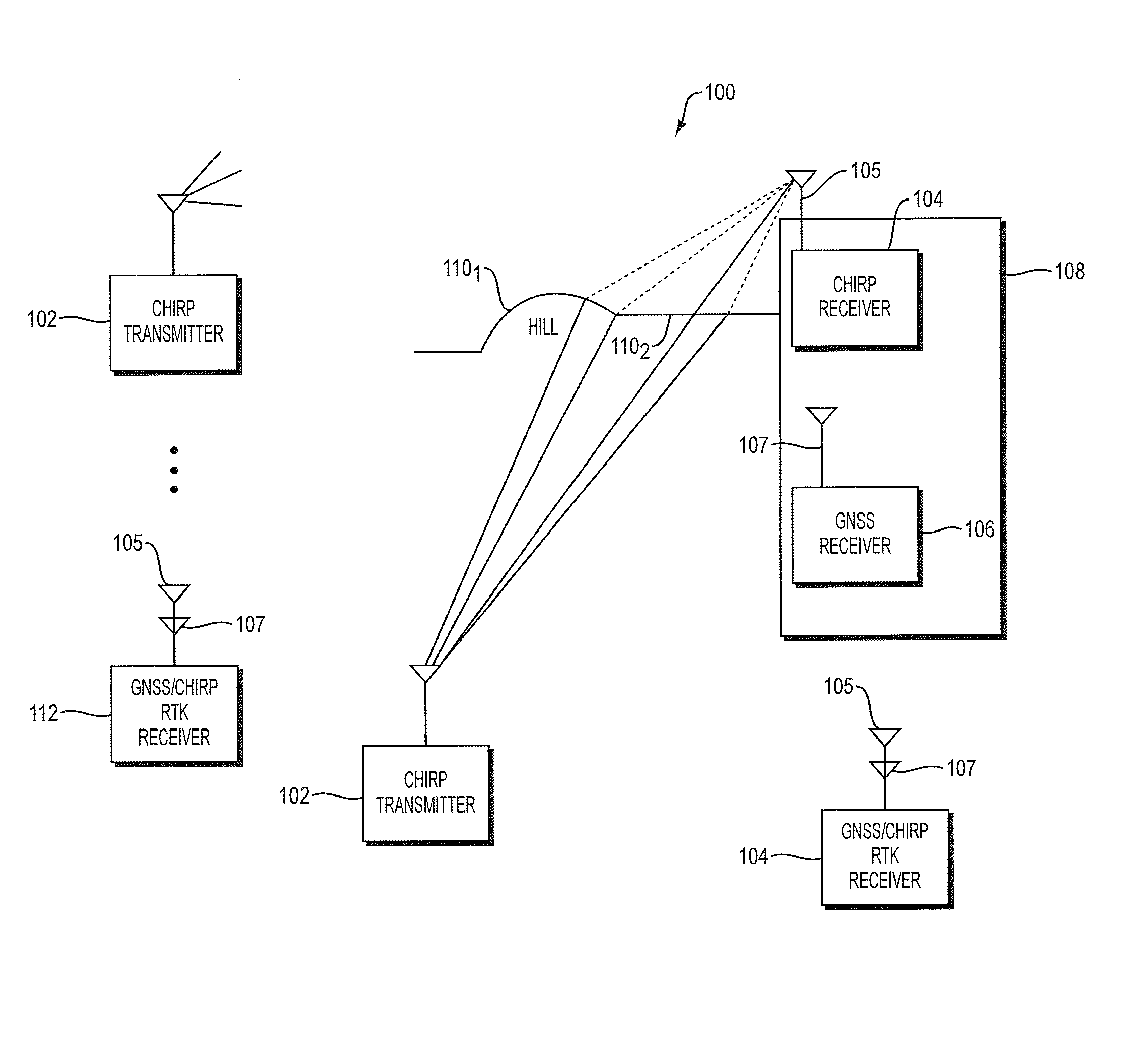
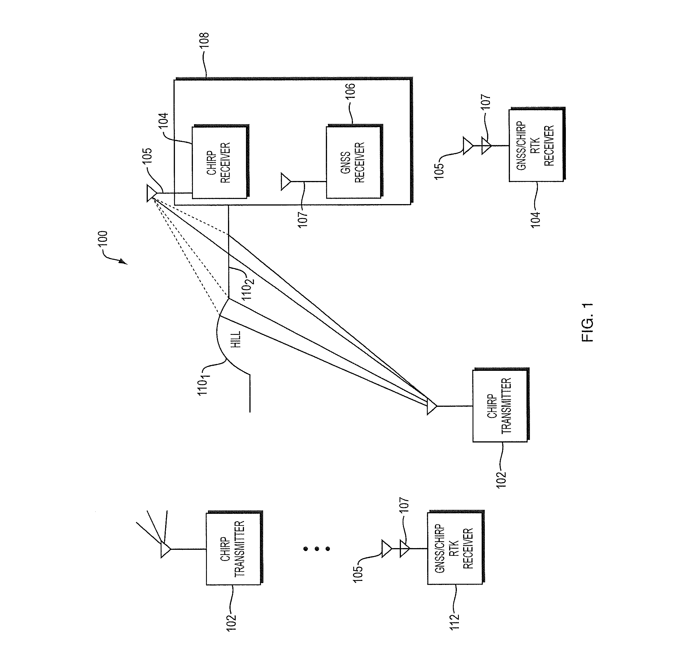
[0021]For ease of explanation, the operations of the system are described first with the co-located GNSS and chirp receivers. The operations are then described for a chirp receiver operating without the co-located GNSS receiver.

[0022]Referring to FIG. 1, a ranging system 100 includes one or more chirp transmitters 102 in known locations, a chirp receiver 104 and a GNSS receiver 106 are co-located on a vehicle 108. Additional GNSS receivers (not shown) may be associated with one or more of the chirp signal transmitters, to provide both time synchronization and the locations of the transmitters based on ranging signals transmitted by GNSS satellites. Alternatively, the chirp transmitters 102 may be placed in predetermined locations or be provided with their time and locations and time synchronization signals at the time of placement using GNSS receivers or other devices to determine the time and locations, and thus, GNSS receivers need not be co-located with the chirp transmitters.

[00...


PUM


Abstract

A chirp receiver processes broadcast chirp signals in the frequency domain to distinguish direct path signals from multipath signals. The receiver processes received chirp signals consisting of respective pulsed frequency sweeps by combining the signals with a synchronized local chirp signal and phase adjusting and concatenating the results over multiple sweeps based on estimated clock phase errors and expected phase rotations of the direct path signals, and produces a sine wave. The phase adjustment and concatenation allows the use of longer Fast Fourier Transforms, which provide increased accuracy of frequency estimation and separate component signals that are very close in frequency. The frequency corresponding to the direct path signal is identified by the lowest frequency bin in which power is above a predetermined noise threshold. The receiver then determines a time delay based on the identified frequency and uses the time delay to calculate accurate clock phase error and position.

Description

BACKGROUND OF THE INVENTION[0001]1. Field of the Invention[0002]This invention relates generally to a ranging receiver and more particularly to a ranging receiver that utilizes chirp ranging signals.[0003]2. Background Information[0004]Ranging systems are used to determine the location or global position of one or more objects relative to one or more transmitters. Radar systems and Global Navigation Satellite Systems (GNSS) are two examples of well known ranging systems.[0005]GNSS receivers determine their global positions based on the time delays associated with code and carrier signals they receive from associated satellites. The GNSS receivers operate in known manners to align locally generated versions of the codes and carriers with the received signal based on correlation measurements. The GNSS receivers then determine the time delay between the known transmission time of the signal and the time of the receipt of the signal based on the phases of the local codes and carriers, a...

Claims


Application Information

Patent Timeline
IPC IPC(8): H04L27/00
CPCG01S11/08G01S19/13H04L27/2657
Inventor PETERSEN, JAMES L.
Owner NOVATEL INC
Features
  • R&D
  • Intellectual Property
  • Life Sciences
  • Materials
  • Tech Scout
  • Unparalleled Data Quality
  • Higher Quality Content
  • 60% Fewer Hallucinations
Learn More