Self-loading microfluidic device and methods of use

a microfluidic device and self-loading technology, applied in biochemistry apparatus and processes, laboratory glassware, instruments, etc., can solve the problems of subjective and variable analysis of these assays, insufficient laboratory availability of instruments, and high labor intensity

Active Publication Date: 2013-05-23
WISCONSIN ALUMNI RES FOUND
View PDF4 Cites 72 Cited by
  • Summary
  • Abstract
  • Description
  • Claims
  • Application Information

AI Technical Summary

Benefits of technology

[0012]In another aspect, the present disclosure is directed to a self-loading microfluidic device including a porous organic polymer and a reaction well, a main channel, a side channel, an inlet port, and a vacuum well, wherein the self-loading microfluidic device has a flow rate of from about 0.25 nL / second to about 5 nL / second and a post-vacuum idle time of from less than about 30 seconds to about 10 minutes.
[0013]In another aspect, the present disclosure is directed to a method of performing an assay using a self-loading microfluidic device. The method includes adding an agent in liquid form to a reaction well of a chamber layer in a self-loading microfluidic device, wherein the self-loading microfluidic device further comprises a channel layer and a cover and wherein the channel layer comprises an inlet port, a vacuum well, a main channel, and a side channel; drying the liquid to form a dried agent; assembling the self-loading microfluidic by contacting the chamber layer, the channel layer, and the cover, wherein the side channel terminates at the reaction well; degassing the self-loading microfluidic device in a low-pressure environment; removing the degassed self-loading microfluidic device from the low-pressure environment; adding a sample solution to the inlet port; flowing the sample solution from the inlet port to fill the reaction well by degas-driven flow; incubating the self-loading microfluidic device; and analyzing the reaction well.

Problems solved by technology

Additionally, the analysis of these assays is subjective and variable.
These assays are well characterized and provide a more quantitative readout than diffusion methods, however, they are generally more labor intensive.
The use of a liquid handling robot to prepare dilution series in multiwell plates can reduce the time and labor involved, however these instruments are expensive and not widely available in laboratories.
However, the strip immunoassay may not be applicable for all immunoassays, and thus, many immunoassays are conducted using microtiter plates, which may require longer assay times and increased reagent use.
Screening large numbers of samples presents a number of problems such as the high cost of equipment, high reagent requirements for performing the assays, and high volumes of solutions.
Thus, microfluidic technology addresses some of the drawbacks associated with the high cost of equipment, high reagent requirements for performing dilution-based and diffusion-based assays, and the high volumes of solutions needed.
These methods, however, require external power sources and other equipment, which can lead to added expense and limit point-of-care applications where the added equipment is unavailable or is of limited access.
Power-free microfluidic pumping methods such as, for example, droplet-based passive pumping, evaporation, capillary flow, and gravity-driven flow, do not require external power sources, but may be limited by other requirements such as, for example, device priming, specific temperature and humidity, and surface treatments.

Method used


Image

  • Self-loading microfluidic device and methods of use
  • Self-loading microfluidic device and methods of use
  • Self-loading microfluidic device and methods of use

Examples


example 1

Fabrication of Microfluidic Devices

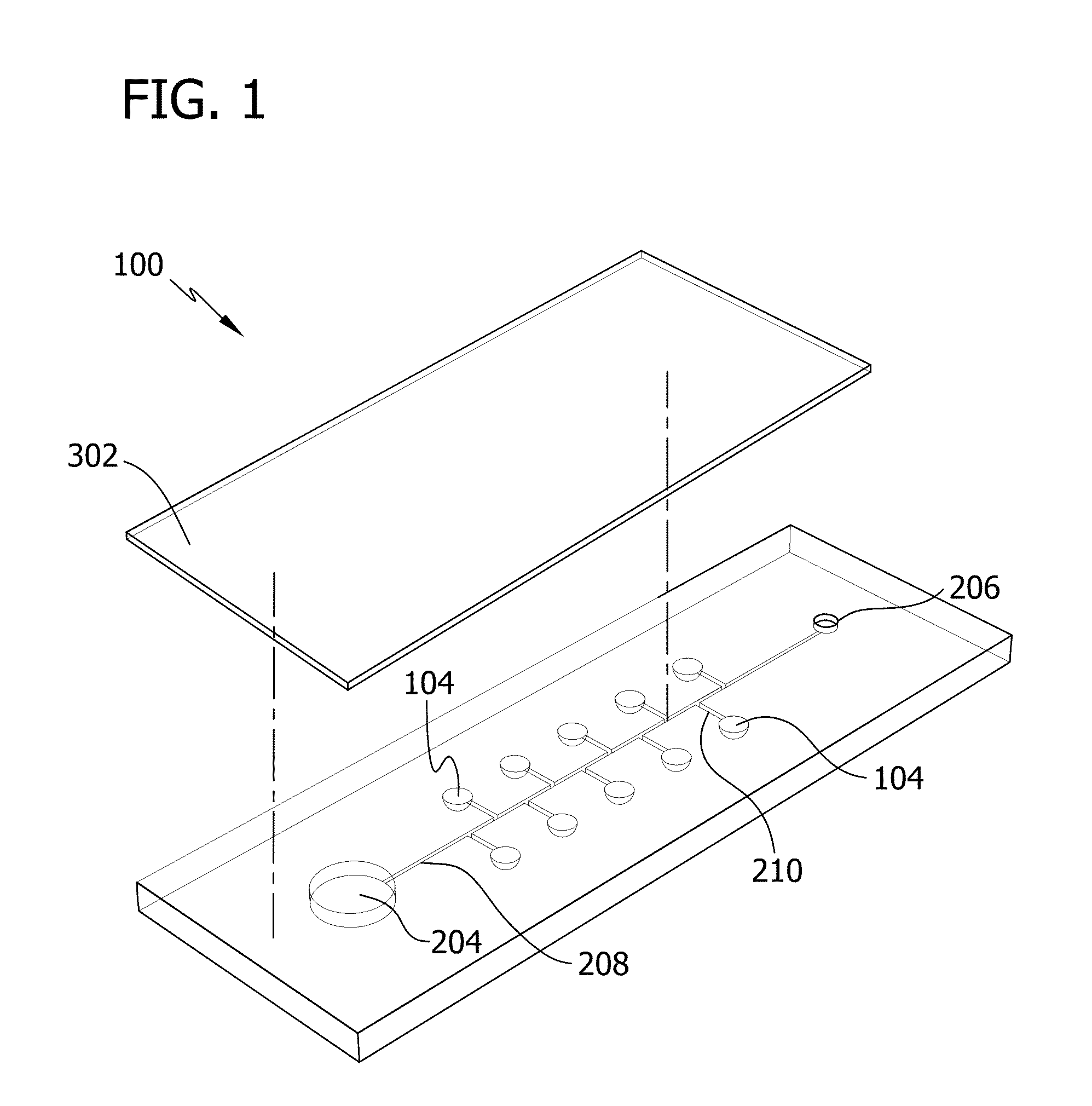
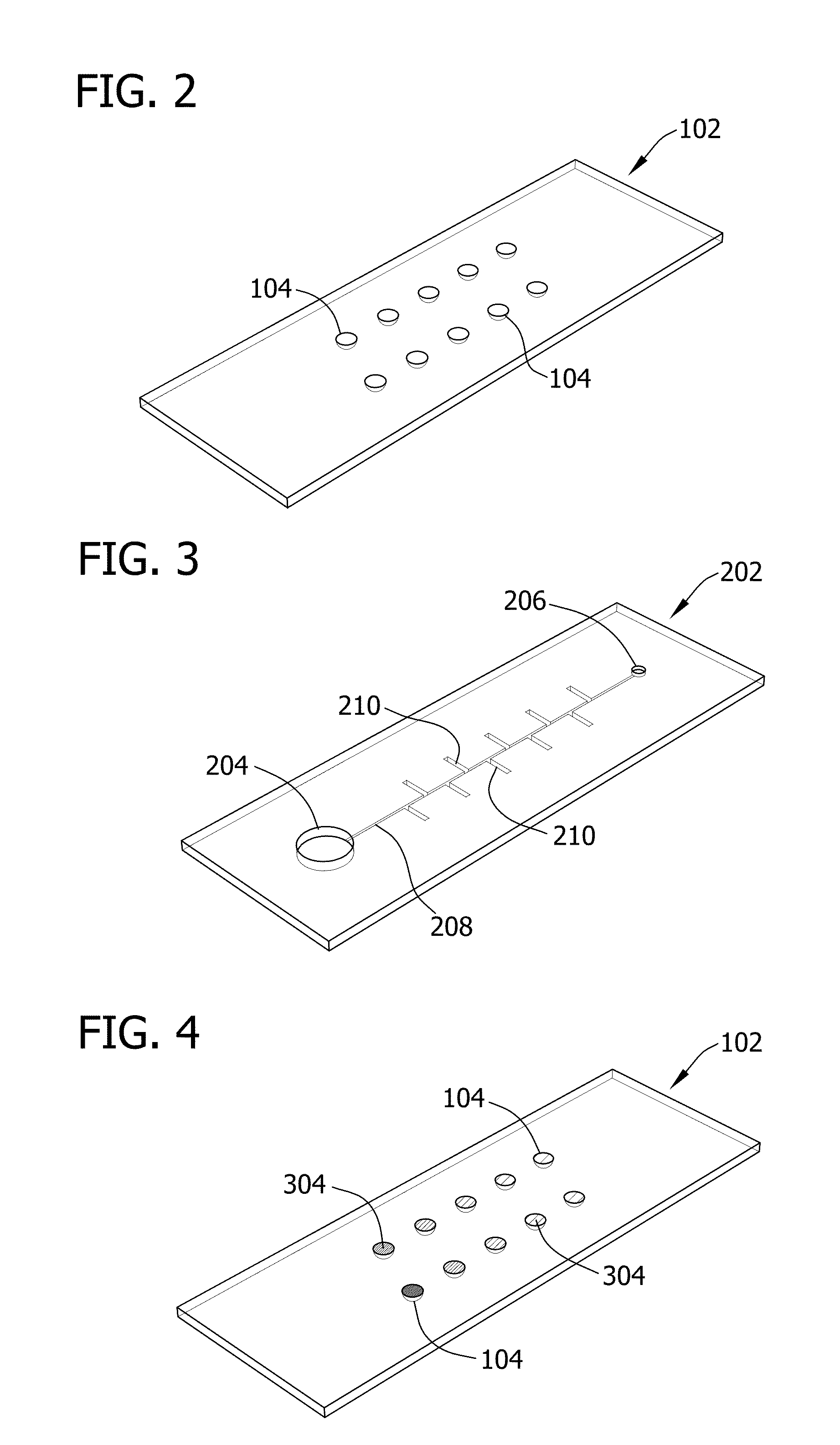
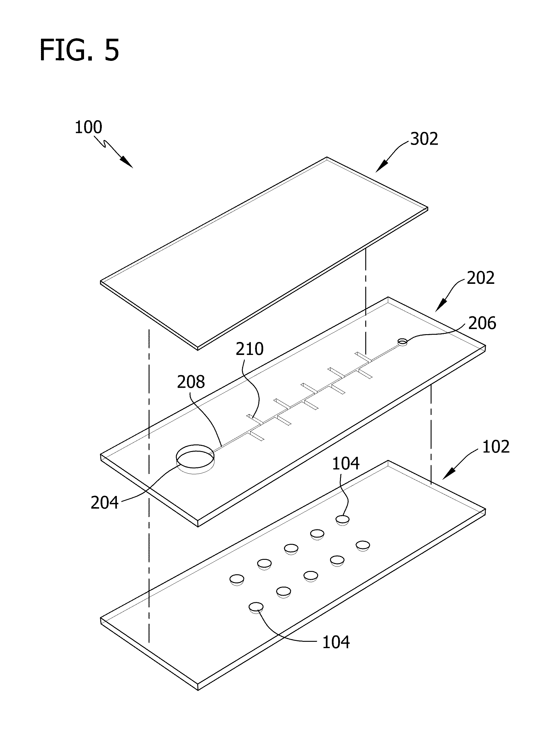
[0092]In this Example, microfluidic devices including ten separate reaction wells were fabricated.

[0093]Specifically, devices were fabricated using soft lithography. Master templates were fabricated in SU-8 photoresist (Microchem) on silicon wafers using photolithography. Separate master templates were prepared for the chamber and channel layers of the device. The photoresist to form the ten reaction wells of the chamber layer was 300-μm high and 2-mm in diameter. The height of the photoresist to form the side channels and main channel of the channel layer was 50 μm and the width of the channel ranged from 150-260 μm. The devices were fabricated using polydimethylsiloxane (PDMS) to take advantage of the permeability of the polymer (for actuation of the sample solution) and the rapid prototyping capabilities. PDMS (Sylgard 184; Dow Corning) was mixed in a 1:10 ratio (base:cross linking agent), cast against the master templates to a height of ˜1-mm, ...

example 2

Loading and Degas-Driven Flow

[0095]In this Example, microfluidic devices prepared as described in Example 1 were used to demonstrate the loading and degas-driven flow in the microfluidic devices.

[0096]Specifically, various concentrations of blue dye were added into all ten reaction wells of the chamber layer of the device. After the liquid of the dye solution was evaporated, the device was assembled and vacuum degassed. The device was then removed from the vacuum and a 20-μL droplet of a solution of yellow dye was pipetted onto the inlet port. The movement of the yellow dye by degas-driven flow was then followed.

[0097]FIG. 23 is a sequence of illustrations depicting the loading and degas-driven flow of the yellow dye placed at the inlet port of the freshly degassed PDMS device. The yellow dye immediately filled the main channel and then filled the reaction wells by flowing through the side channel. The vacuum well continued to draw in the yellow dye until the droplet was consumed, a...

example 3

Controlling Concentration of Agents

[0098]In this Example, the reproducibility of controlling the concentration of agents in the reaction wells was determined.

[0099]Specifically, five devices were fabricated as described above and various concentrations of fluorescein (18-99 μM) were added to each reaction well and dried by evaporation. After the liquid was evaporated, the device was assembled and vacuum degassed. After degassing, a 20 μL droplet of deionized water was introduced at the inlet. After the liquid was introduced and isolated in the reaction wells to reconstitute the dried fluorescein, the fluorescence intensity of the reaction wells was imaged and quantified using ImageJ (FIG. 25). The mean fluorescence intensity of each chamber (n=5) between the five devices followed a linear trend (FIG. 26).


PUM

PropertyMeasurementUnit
flow rateaaaaaaaaaa
timeaaaaaaaaaa
timeaaaaaaaaaa

Abstract

Microfluidic devices and methods for conducting chemical assays and biological assays using microfluidic devices are disclosed. The microfluidic devices do not require external connections, tethers, tubing, valves and actuators. The microfluidic devices are useful in methods for analyzing a wide variety of chemical and biological assays such as, for example, molecule-molecule interactions, enzyme-substrate interactions, molecule identification, minimum inhibitory concentrations, therapeutically effective amounts, and toxic amounts.

Description

BACKGROUND OF THE DISCLOSURE[0001]The present disclosure relates generally to microfluidic technology. More particularly, the present disclosure relates to self-loading microfluidic devices. The present disclosure further relates to methods of using the self-loading microfluidic devices for chemical assays and biological assays.[0002]The search for new therapeutic agents involves rapidly screening test compounds in chemical assays and biological assays to identify lead compounds for further development. Once lead compounds are identified, additional screening may be needed to identify therapeutically effective amounts and toxicity levels. Screening therapeutic agents is important for patient treatment and for preventing the prescription of ineffective pharmaceuticals. For example, determining the minimum inhibitory concentration (MIC) of antibiotics against bacteria is important for preventing the prescription of ineffective antibiotics that may lead to the spread of antibiotic-resi...

Claims


Application Information

Patent Timeline
Patent Type & Authority Applications(United States)
IPC IPC(8): C12Q1/70G01N1/00G01N33/48C12Q1/04G01N33/566C12Q1/68B01L3/00C12Q1/02
CPCG01N33/54386B01L3/5027B01L3/502707B01L2200/16B01L2300/0816Y10T436/25B01L2300/0887B01L2400/0406B01L2400/049B01L3/50273Y10T436/143333B01L2300/0864B01L3/502715B01L2300/12B01L2200/10B01L2200/0642G01N33/54388
Inventor WEIBEL, DOUGLASCIRA, NATHANIEL JAMES
Owner WISCONSIN ALUMNI RES FOUND
Why Eureka
Try Eureka