Methods for Super Heated Steam Generation

a super-heated steam and generator technology, applied in the direction of water feed control, automatic control of ignition, separation process, etc., can solve the problems of insufficient natural internal pressure to push oil to the surface, prior art stream generators that have been limited in producing large volumes of steam, and able to recover approximately twenty-percent of original oil, so as to improve the super-heating ability and efficiency heat adjacent, the effect of minimizing undesirable and degrading thermal gradients

Inactive Publication Date: 2013-05-30
TRIMETEOR OIL & GAS CORP
View PDF32 Cites 24 Cited by
  • Summary
  • Abstract
  • Description
  • Claims
  • Application Information

AI Technical Summary

Benefits of technology

[0047]Another object is to provide superheated steam generators of enhanced superheat capabilities.
[0048]Another basic object of this invention is to provide superheated steam generators wherein water flow to the pressure vessels is precisely monitored and automatically controlled.
[0049]A related object is to provide a unique, modularized electrode configuration that efficiently heats adjacent, superheater pressure vessels non-destructively, while minimizing undesirable and degrading thermal gradients.

Problems solved by technology

It has long been recognized in the art that, when the natural drive energy of an oil reservoir or well decreases over time, natural internal pressure is inadequate to push oil to the surface.
Because of the relationship between temperature, volume and pressure, prior art stream generators have been limited in producing large volumes of steam because of the resultant variance in other steam parameters.
However, it is typically only able to recover approximately twenty-percent of the Original Oil in Place (OOIP), compared to steam flooding, which has been reported to recover over fifty-percent of OOIP.
A recognized difficulty in the art relates to the generation of superheated steam at proper temperatures, pressures, and volumes.
However, with the latter device, steam output temperatures vary widely, and critical operating parameters including tank and water temperature, output pressure and output volume are not dynamically controlled.
Liquid levels within various tanks can vary constantly, resulting in irregular vaporization.
Temperature fluctuations of between 400° and 600° F. were experienced, compromising operating the efficiency of the steam generation system.
However, one common weakness in prior devices has been the inability to reliably and virtually continuously generate and deliver a large volume of high temperature, superheated steam.
One problem has been experienced with the electrodes used to heat internal vaporization or evaporation tanks, and with other critical components.
Because of the resultant thermal expansion of the metal components, and the various different coefficients of expansion that characterize parts of different construction materials, extreme stresses occur, as the dimensions of critical parts expand during heat-up.
Most disturbingly, failures associated with such mechanisms as creep and creep fatigue occur over time in threaded pipe fittings employed with steam machines of the type described in the latter patent.
The stress problem has caused component failure in the past, necessitating time consuming and expensive field repairs.
For example, because of the traditional mounting techniques used for high temperature tanks that are bathed within liquid lead during operation, component failures have been frequent.
One recurrent problem, for example, has been burn-out or failure of critical electrical heating elements disposed within each heater assembly.
The configuration of internal parts such as the electrode heater elements, and the lack of precision, militate against proper dynamic control of operating points necessitated by manual operation.
After substantial field tests of the apparatus described in the aforementioned application, it has been concluded that the use of liquid lead for heat transfer is a fundamental problem.
Moreover, reliance upon thermal conduction as a heat transfer mechanism appears to be a flawed approach, when compared to the other methods of heat transfer that may be available, such as convention and radiation heat transfer modes.
Critical parts that must be removed are often partially captivated in the solid, unwieldy mass of cooled lead.
Even worse, when component failure or breakage leads to a crack or the formation of pin holes, molten lead may leak from the tanks or pressure vessels.
The repair technician is thus faced with a time consuming job requiring substantial lead clean-up.
Solid lead waste is tedious to remove, requiring blow torches and the liberal use of protective gear and clothing.
The environmentally proper disposal of lead waste is difficult as well.
Simple, manually operated valves in water control pathways, for example, are insufficient as they are unable to respond in real time to dynamic operating conditions.

Method used


Image

  • Methods for Super Heated Steam Generation
  • Methods for Super Heated Steam Generation
  • Methods for Super Heated Steam Generation

Examples


Embodiment Construction

[0110]The entire disclosure of previously filed and copending U. S. utility patent application Ser. No. 12 / 59000,919, entitled “Super Heated Steam Generator With Slack Accommodating Heating Tanks,” filed Nov. 15, 2009, is hereby incorporated by reference as if fully set forth herein.

[0111]A. General Hardware:

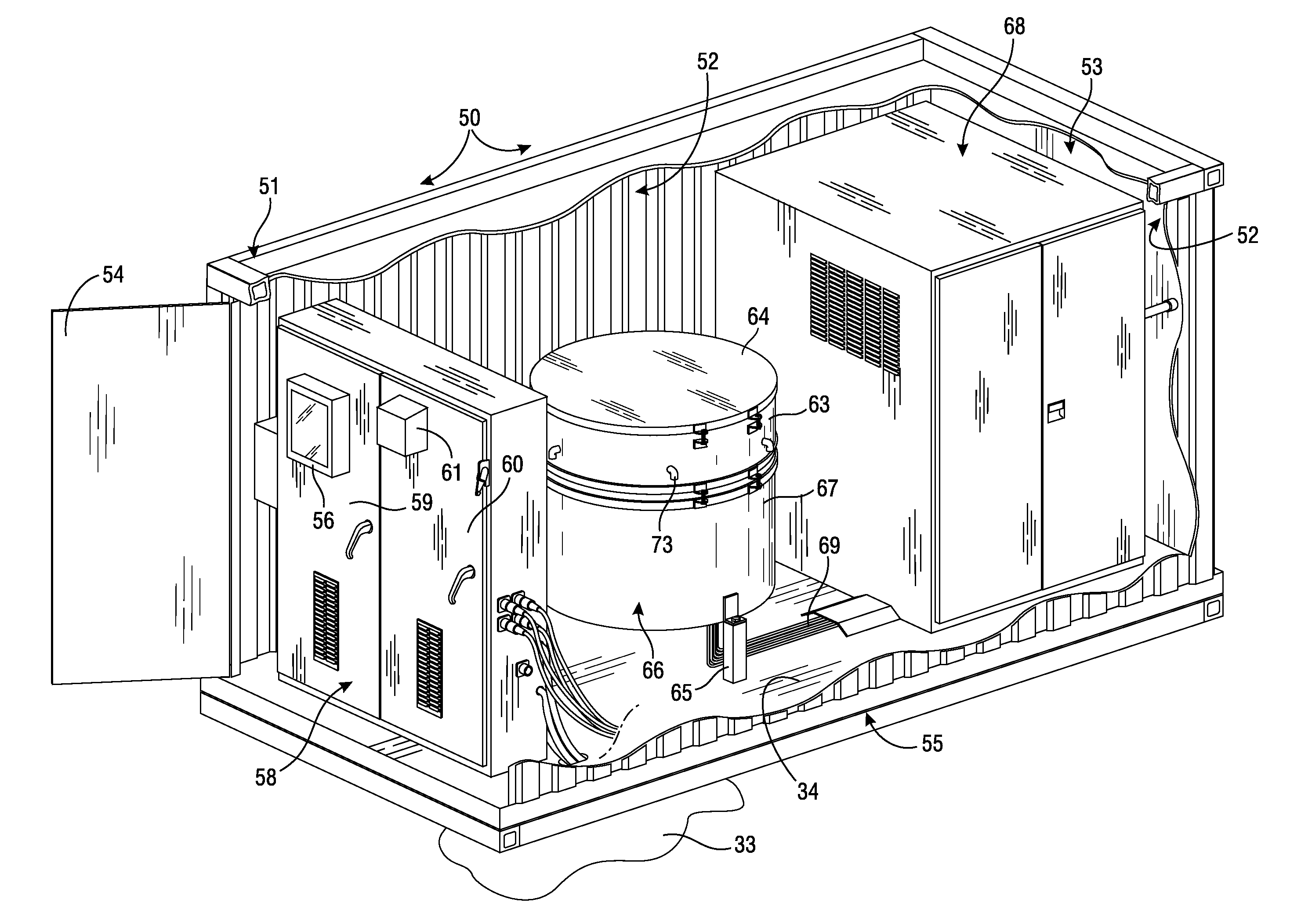
[0112]Referring initially to FIG. 1 of the appended drawings, a modularized, superheated steam generator constructed generally in accordance with the best mode of the invention has been generally designated by the reference numeral 50. Generator 50 comprises a rigid, preferably metallic enclosure 51 that is generally in the form of a parallelepiped, and which is preferably similar in size to a standard shipping container. Enclosure 51 comprises a rigid, channel steel frame with side walls 52, a rear end 53, and a front access door 54 that exposes the enclosure interior. Enclosure 51 includes a rigid, lower base 55 adapted to be disposed upon a suitable supporting surface 33, whi...


PUM


Abstract

Modularized, superheated steam generators comprise a steam module (46), a thermocouple module (41), and an electrode module (45) assembled within a containment enclosure (66). The multi-stage steam module (46) comprises a plurality of first stage pressure vessels (77) surrounding and feeding a second stage pressure vessel (78). The steam module (46) is coaxially surrounded by insulation (48) disposed within a cylindrical shroud (72). The electrode module (45) radiantly heats the steam module with resistive heating elements (119). The thermocouple module (41) includes thermocouples monitoring first stage temperatures within and between pressure vessels (77). PLC computer SCADA software (600) operates the generators. Thermocouple data is analyzed to control heater temperatures, the water feeding system (340), and outputted steam temperature. PLC software (600) provides operating logic (602) establishing a start up subroutine (602), a ramp up subroutine (603), a steady state subroutine (605), and a shut down subroutine (606).

Description

CROSS-REFERENCE TO RELATED APPLICATION[0001]This application is based upon prior pending U.S. Provisional Patent Application Ser. No. 61 / 629,802, Filed Nov. 28, 2011, entitled “High Power Method and Apparatus for Generating Super Heated Steam,” by inventors Richard B. Graibus, Charles T. McCullough, Edward L. Sulitis, and Jimmy L. Turner, and priority based upon said prior application is claimed.BACKGROUND OF THE INVENTION[0002]1. Field of the Invention[0003]The present invention relates generally to high temperature, superheated steam generators for use in recovering crude oil of low specific gravity, the enhancement of reservoir drive, and deparrafinization. More particularly, the present invention relates to enhanced, computer controlled, high-powered superheated steam generators for producing superheated steam.[0004]2. Description of the Related Art[0005]It has long been recognized in the art that, when the natural drive energy of an oil reservoir or well decreases over time, na...

Claims


Application Information

Patent Timeline
Patent Type & Authority Applications(United States)
IPC IPC(8): F22B1/28F22B35/00F22G1/06F22G5/00F22B27/04F22D1/00
CPCF22B1/287F22B27/14F22D5/26F22G5/20F22B1/285F22B35/005F22B35/104F22D1/003F22G1/06F22G5/00F22B27/04
Inventor GRAIBUS, RICHARD B.TURNER, JIMMY L.MCCULLOUGH, CHARLES T.WILLIAMS, DENNIS K.SULITIS, EDWARD L.
Owner TRIMETEOR OIL & GAS CORP
Why Eureka
Try Eureka