Square lithium secondary battery

a lithium secondary battery and lithium-ion battery technology, applied in batteries, wound/folded electrode electrodes, sustainable manufacturing/processing, etc., can solve the problems of reducing discharge capacity, difficult to precisely remove or flake the active material layer in the wound body area, and difficulty in electrode manufacturing technology, etc., to achieve high charge, increase surface area, and increase the density of projections

Active Publication Date: 2013-06-06
SEMICON ENERGY LAB CO LTD
View PDF2 Cites 36 Cited by
  • Summary
  • Abstract
  • Description
  • Claims
  • Application Information

AI Technical Summary

Benefits of technology

[0029]The negative electrode active material mixture layer may have a structure including a common portion and a plurality of projection portions projecting from the common portion. With such a structure, the density of projections can be increased in the negative electrode active material mixture layer, whereby the surface area can be increased. Thus, a square lithium secondary battery with high charge and discharge capacity can be obtained.
[0030]By using any of the aforementioned structures, the square lithium secondary battery has improved reliability while maintaining high discharge capacity.
[0031]When a surface of the active material is in contact with an electrolyte solution in the lithium secondary battery, the electrolyte solution and the active material react with each other, so that a film is formed over the surface of the active material. The film is c

Problems solved by technology

However, it is in practice very difficult for the electrode manufacturing technology to provide a wound body in a square lithium secondary battery in such a manner that an active material mixture layer is not formed in a bend with a small radius of curvature as described in Patent Document 1 or 2.
However, in terms of the position control accuracy in manufacture of electrodes, it is difficult to precisely remove or flake the active material layer in that area of the wound body.
Furthermore, in the square lithium secondary battery disclosed in Patent Document 1 or 2, the active material mixture layer is not formed in a bend with a small radius of curvature, which leads to a reduction in discharge capacity.
Th

Method used


Image

  • Square lithium secondary battery
  • Square lithium secondary battery
  • Square lithium secondary battery

Examples


embodiment 1

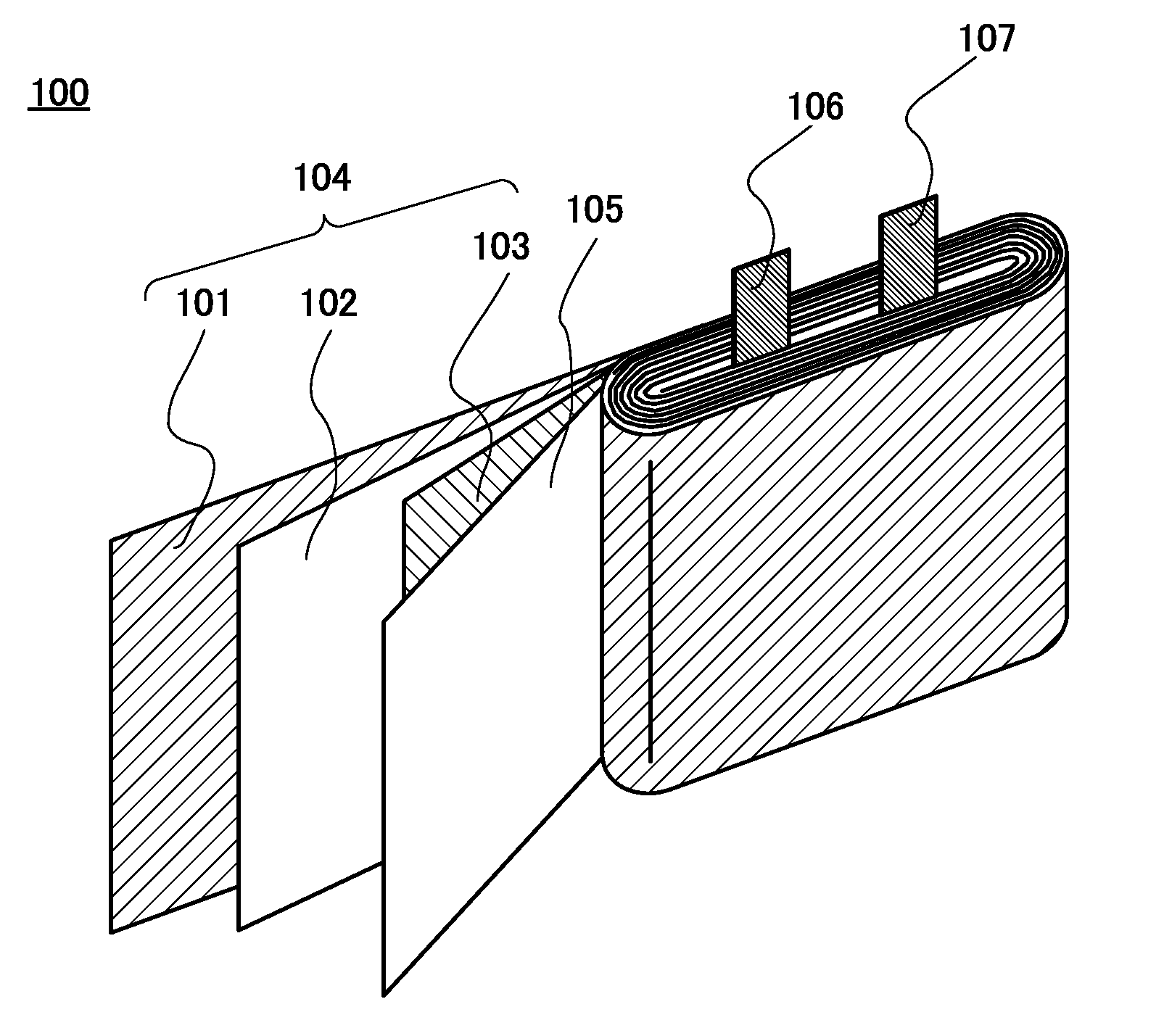
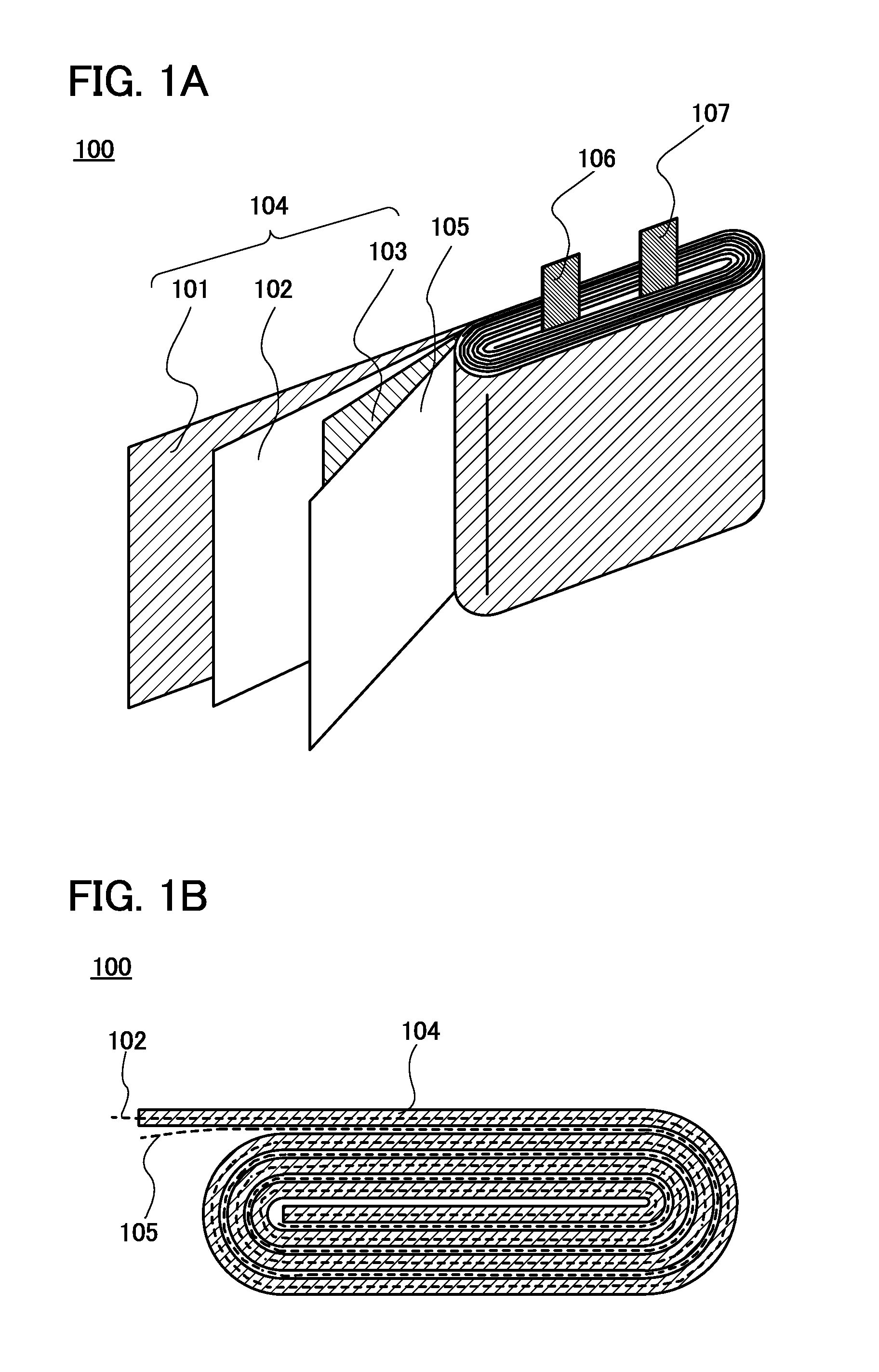
[0049]In this embodiment, a structure of an electrode sheet for a square lithium secondary battery will be described with reference to FIGS. 1A to 1B, FIGS. 3A to 3C, and FIGS. 4A and 4B. In the structure, a plurality of openings are formed in a part of an active material mixture layer which corresponds to a bend in a collective sheet in a wound body. The electrode sheet refers to a positive electrode sheet and a negative electrode sheet.

[0050]A lithium secondary battery refers to a secondary battery in which lithium ions are used as carrier ions. As examples of carrier ions which can be used instead of lithium ions, alkali-metal ions such as sodium ions and potassium ions; alkaline-earth metal ions such as calcium ions, strontium ions, and barium ions; beryllium ions; magnesium ions; and the like are given.

[0051]FIG. 1A is a schematic view of a wound body 100 incorporated in a square lithium secondary battery. A positive electrode sheet and the like shown in FIG. 1A are spread for ...

embodiment 2

[0072]In this embodiment, examples of the shape or structure of the electrode sheet, which are different from those shown in Embodiment 1, will be described with reference to FIGS. 7A to 7C.

[0073]FIG. 7A is the same diagram as FIG. 3B, illustrating the shape or structure of the electrode sheet shown in Embodiment 1. In the region 111b with the plurality of openings, the plurality of openings 114 are arranged at regular intervals in the longitudinal direction of the electrode sheet. In FIG. 7B, in the region 111b with the plurality of openings, the plurality of openings 114 are not arranged at regular intervals, but the distance between the openings 114 is gradually decreased closer to the center of the region 111b while being gradually increased closer to the edge. When the openings in the region 111b with the plurality of openings are arranged in such a manner, the margin to compensate for the misalignment in the winding process can be further increased as compared to that in Embod...

embodiment 3

[0076]In this embodiment, examples of the shape or structure of the electrode sheet, which are different from those shown in Embodiment 1 or 2, will be described with reference to FIG. 8.

[0077]FIG. 8 illustrates a cross-sectional structure of the electrode sheet in the longitudinal direction in this embodiment. In the region 111b with the plurality of openings of the electrode sheet, a groove 116 of the current collector, which corresponds to the opening 114, is provided in an exposed area of the positive electrode current collector 110. The groove is not formed in another area of the positive electrode current collector 110 which is in contact with the positive electrode active material mixture layer 111. Accordingly, the surface of the positive electrode current collector 110 in the opening 114 is positioned at an inner side than the surface of the positive electrode current collector 110 in the island pattern 115 made of the positive electrode active material mixture layer 111. W...


PUM


Abstract

A square lithium secondary battery includes a wound body in which a collective sheet in which a positive electrode sheet and a negative electrode sheet overlap each other with a first separator interposed therebetween is wound while a second separator is put inside the collective sheet. An active material mixture layer on one or both surfaces of at least one of the positive electrode sheet and the negative electrode sheet includes a region with a plurality of openings and a region with no opening. At least a bent portion of the collective sheet is covered with the region with the plurality of openings.

Description

BACKGROUND OF THE INVENTION[0001]1. Field of the Invention[0002]The present invention relates to a square lithium secondary battery.[0003]2. Description of the Related Art[0004]With recent advances in environmental technology, power generation devices (e.g., solar power generation devices) which pose less burden on the environment than in conventional power generation methods have been actively developed. Concurrently with the development of power generation technology, development of power storage devices such as lithium secondary batteries, lithium-ion capacitors, and air cells has also been advanced.[0005]In particular, demand for lithium secondary batteries has rapidly grown with the development of the semiconductor industry, for the purpose of use in the next generation of clean energy vehicles such as hybrid electric vehicles (HEV), electric vehicles (EV), and plug-in hybrid electric vehicles (PHEV); personal digital assistants such as cellular phones, smart phones, and laptop...

Claims


Application Information

Patent Timeline
IPC IPC(8): H01M10/0587H01M50/103
CPCH01M10/052Y02T10/7011H01M2002/0205H01M10/0587H01M4/386Y02E60/122H01M50/103H01M4/38Y02E60/10Y02P70/50H01M2220/30H01M2220/20Y02T10/70H01M10/0431H01M10/0525
Inventor HOSOYA, KUNIOKIMURA, KUNIO
Owner SEMICON ENERGY LAB CO LTD
Why Eureka
Try Eureka