

Membrane reactor
a membrane reactor and reactor technology, applied in the direction of electrochemical generators, electrolytic organic production, sustainable manufacturing/processing, etc., can solve the problems of low conversion efficiency and flux of electrolytic cells, and limit the use of electrolytic cells for commercialization applications
- Summary
- Abstract
- Description
- Claims
- Application Information
AI Technical Summary
Benefits of technology
Problems solved by technology
Method used
Image

Examples
example 1
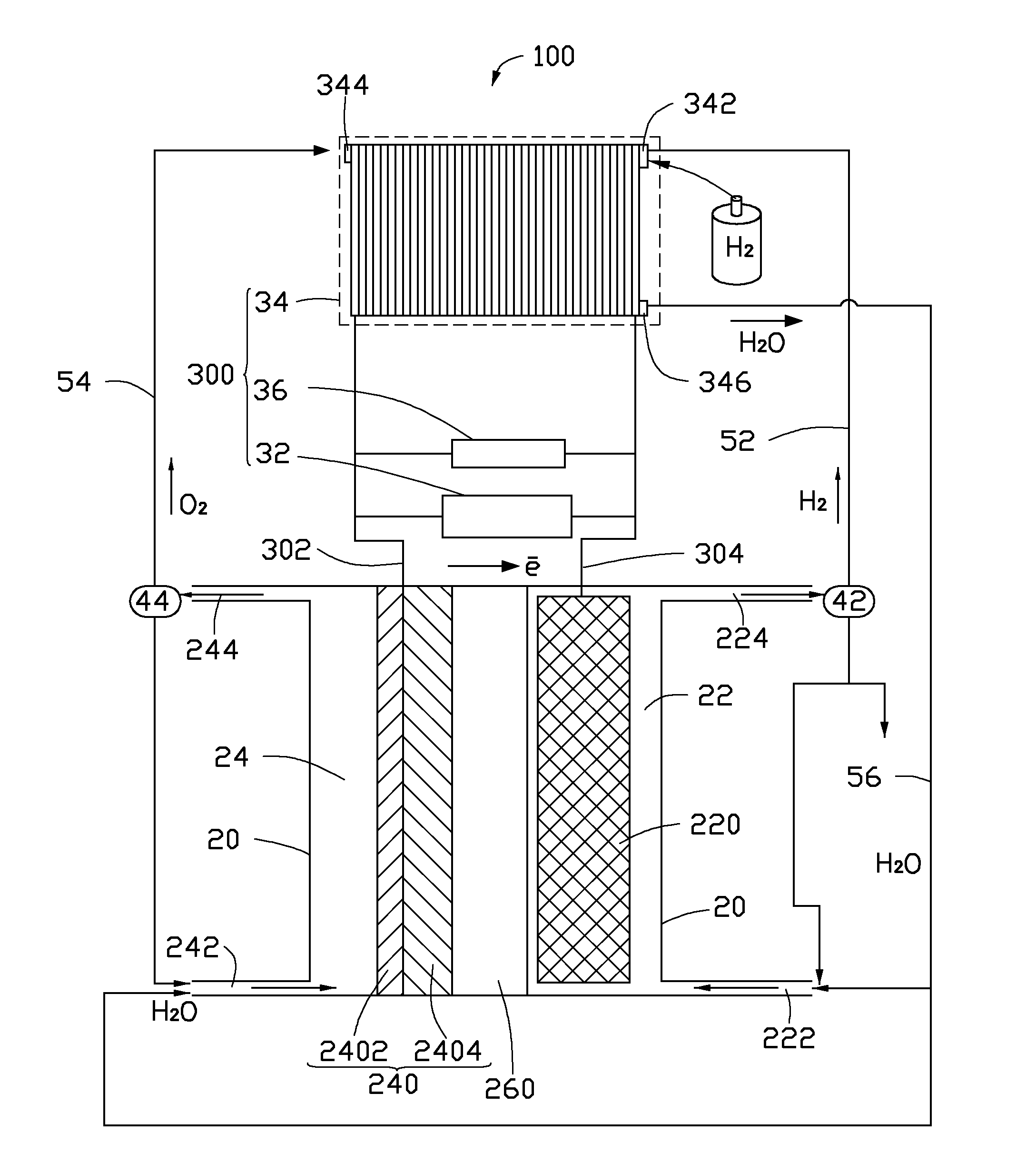
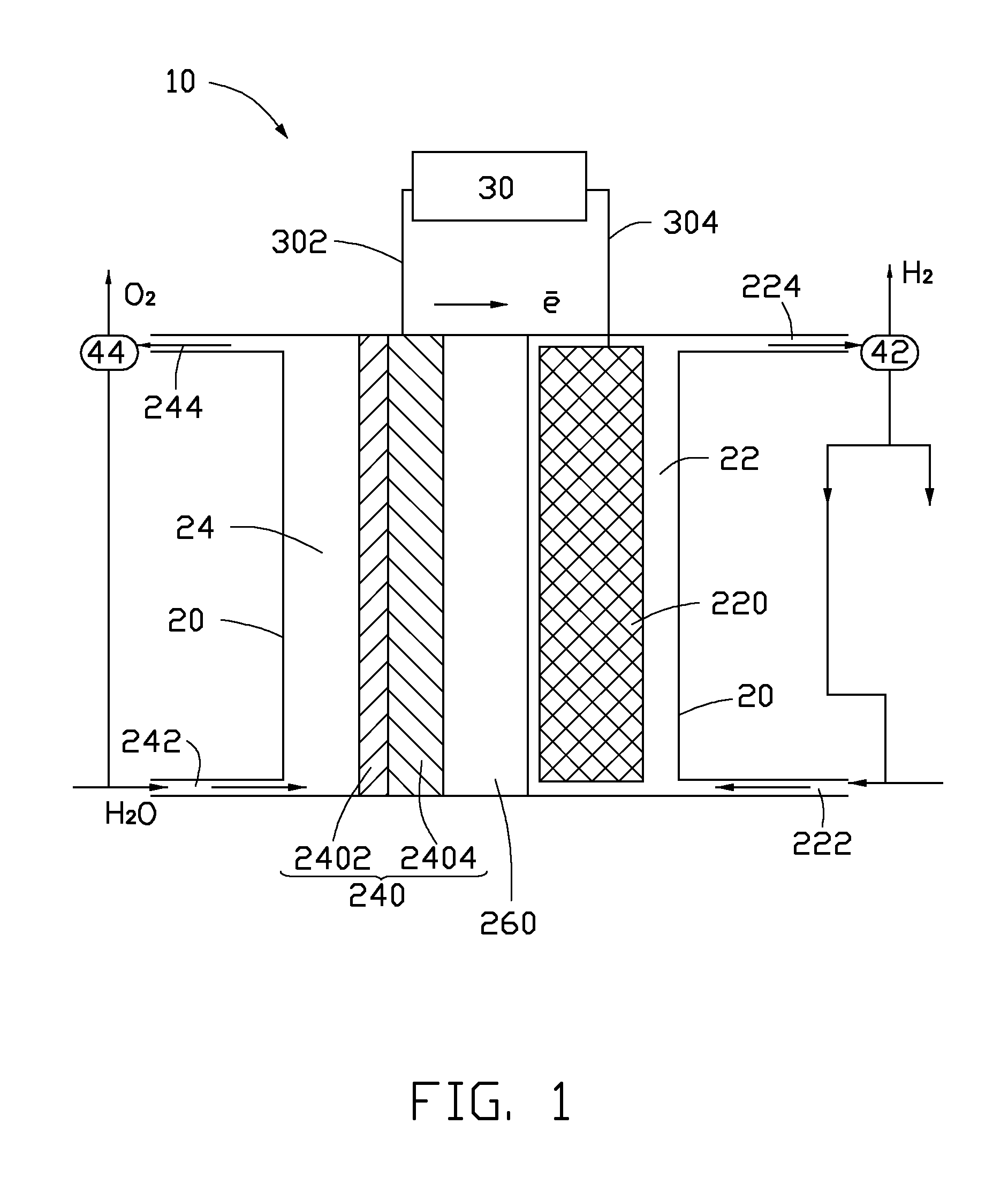
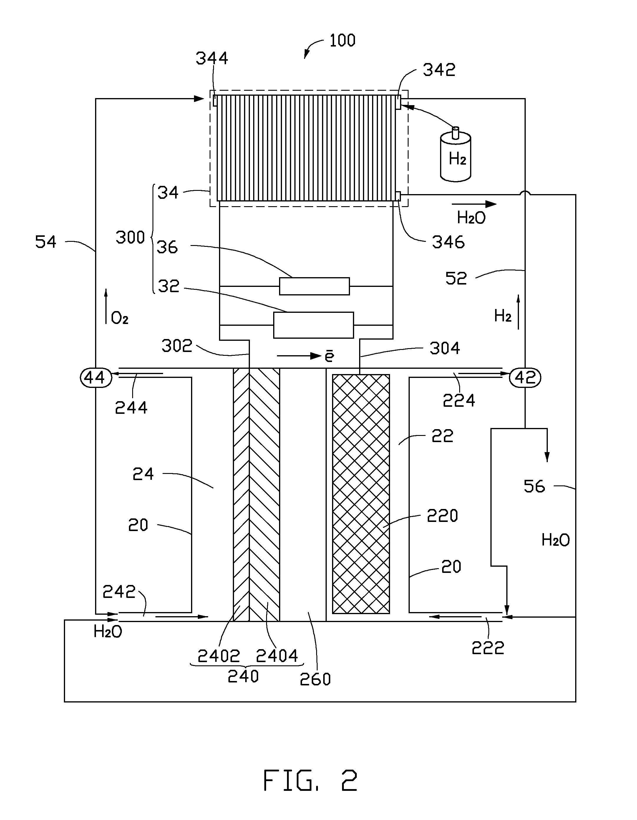
[0041]In the cathode 220 of the membrane reactor 10 or 100, a porous titanium mesh with a thickness of about 10 millimeters and a porosity of about 60% is used as the porous conductive layer 2202. Highly dispersed Sn / Cu alloy particles are used as the cathode catalyst particles 2204 deposited in the holes of the porous conductive layer 2202. In the anode 240 of the membrane, a carbon paper is used as the porous diffusion layer 2402, and nickel powders as the anode catalyst are deposited on the surface of the carbon paper to form the anode 240. The perfluoro sulfonate membrane enhanced by a polytetrafluoroethylene network with a thickness of about 150 micrometers is used as the solid electrolyte separator 260. The solid electrolyte separator 260 and the anode 240 are hot pressed to form a composite structure. An air-cooled proton exchange membrane fuel cell is used as the charge power supply 34.
[0042]Purified CO2 gas generated from a coal-fire power station is boosted to about 2 atmo...
example 2
[0043]The membrane reactor 10 and the converting process of the CO2 of this example is the same as the membrane reactor 10 of Example 1, except that a porous nickel mesh with a thickness of about 2.1 millimeters and a porosity of about 31% is used as the porous conductive layer 2202. Cd / In alloy particles which are electroplated on the support skeleton of the porous nickel mesh are used to form the cathode catalyst particles 2204. A mixture of the MnO2 powders and Ag powders is used to form the anode catalyst layer 2404. The solid electrolyte separator 260 is the perfluorocarboxylic acid membrane enhanced by a porous polytetrafluoroethylene film with a thickness of about 52 micrometers. The self-humidifying proton exchange membrane fuel cell is used as the charge power supply 34. The CO2 gas is generated from a heating boiler. The cathode electrolyte is a KHCO3 water solution. The electrolytic voltage is about 3.5 V. The expected products are potassium formate. The current efficienc...
example 3
[0044]The membrane reactor 10 and the converting process of the CO2 gas of this example is the same as the membrane reactor 10 of Example 1, except that a porous stainless steel mesh with a thickness of about 20 millimeters and a porosity of about 90% is used as the porous conductive layer 2202. A mixture of Bi particles and Zn particles which are electroplated on the support skeleton of the porous stainless steel mesh is used to form the cathode catalyst particles 2204. A porous nickel mesh is used as the porous diffusion layer 2402. A mixture of the LaNi5 powders and Co powers is sprayed on the surface of the porous nickel mesh to form the anode catalyst layer 2404. The solid electrolyte separator 260 is a composite of the enhanced perfluorocarboxylic acid membrane and perfluorocarboxylic acid membrane with a thickness of about 200 micrometers. The solid oxide fuel cell is used as the charge power supply 34. The CO2 gas is purified and boosted to about 5 atmosphere of pressure. Th...
PUM
| Property | Measurement | Unit |
|---|---|---|
| Thickness | aaaaa | aaaaa |
| Thickness | aaaaa | aaaaa |
| Thickness | aaaaa | aaaaa |
Abstract
Description
Claims
Application Information