Electrochromic nickel oxide simultaneously doped with lithium and a metal dopant

a nickel oxide and lithium technology, applied in the field of electrochromic materials, can solve the problems of undesirable side reactions, difficult intercalation of lithium into nio based materials, and how dark an electrochromic device can becom

Active Publication Date: 2013-07-18
SAGE ELECTROCHROMICS +1
View PDF0 Cites 70 Cited by
  • Summary
  • Abstract
  • Description
  • Claims
  • Application Information

AI Technical Summary

Benefits of technology

[0010]The following embodiments and aspects thereof are described and illustrated in conjunction with systems, tools and methods that are meant to be exemplary and illustrative, no

Problems solved by technology

One limitation on how dark an electrochromic device can become is how much charge can be stored in the counter electrode layer.
Unfortunately, it has been difficult to intercalate lithium into NiO based materials as a result of the material's compact crystalline structure.
As such, higher voltages must be applied to such materials to intercalate lithium, in order to drive the electrochromic response at a reasonably fast rate, which leads to undesirable side reactions.
Although it may be relatively easy to manufacture a counter electrode layer capable of coloring anodically in an aqueous medium, it is difficult to produce a complete device capable of long-term stability.
This yellow color is only slightly modulated by li

Method used


Image

  • Electrochromic nickel oxide simultaneously doped with lithium and a metal dopant
  • Electrochromic nickel oxide simultaneously doped with lithium and a metal dopant
  • Electrochromic nickel oxide simultaneously doped with lithium and a metal dopant

Examples


example 1

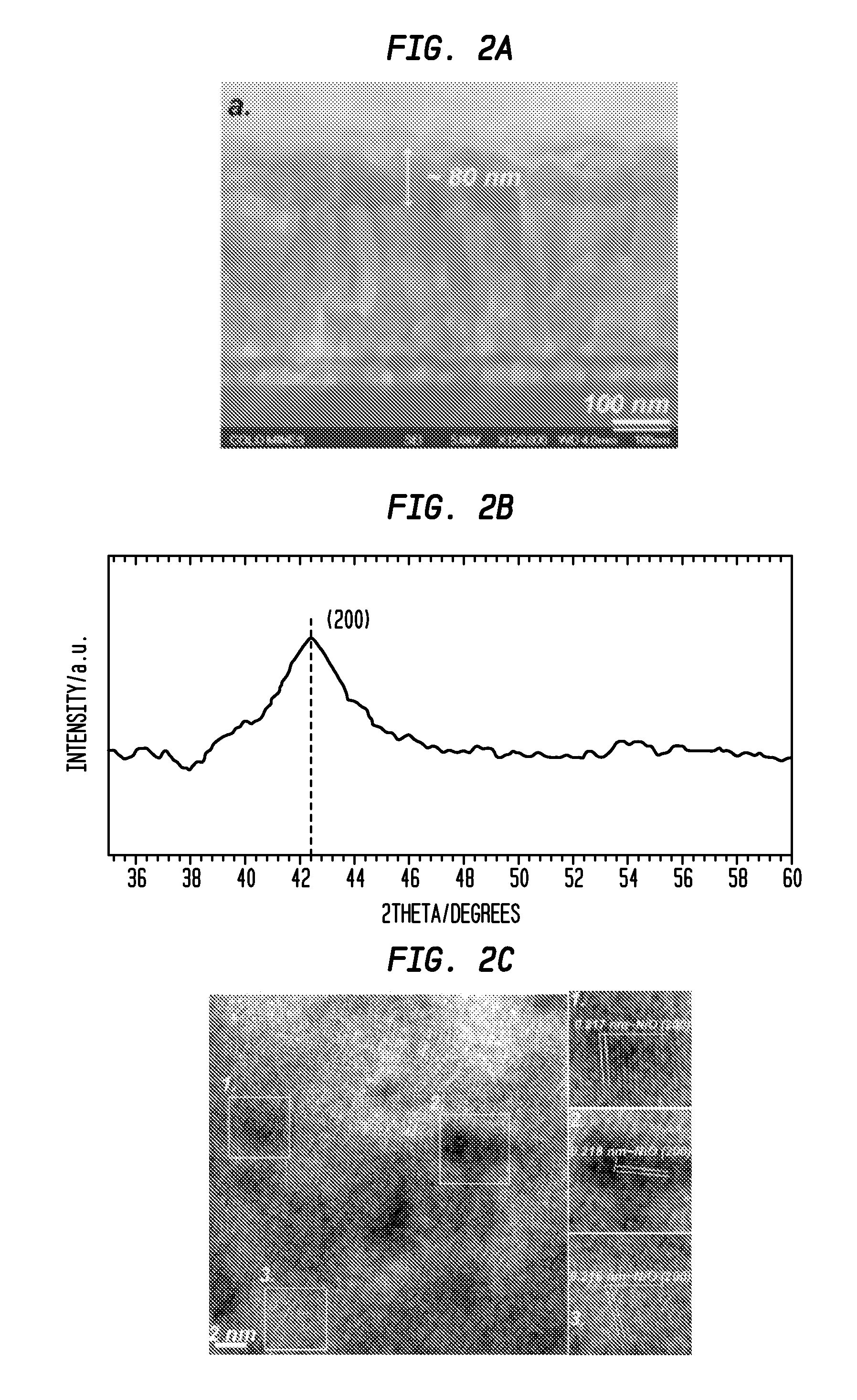
[0127]Structural characterization results for the as-deposited Li2.34NiZr0.28Ox films prepared by RF magnetron sputtering are shown in FIG. 2. Cross-sectional scanning electron microscopy (SEM) image (FIG. 2a) shows the film thickness is ca. 80 nm, which is thinner than reported nickel oxide-based anodic electrodes.

[0128]FIG. 2b provides the X-ray diffraction (XRD) spectrum for the as-deposited Li2.34NiZr0.28Ox film. Only the (200) peak is observed in the spectrum indicating that nickel oxide nanocrytallites were preferentially oriented along the direction. Additionally, the diffraction angle (2θ=42.5°) was shifted towards a lower value relative to the face center cubic NiO indicating that the lattice constant of the nickel oxide-based material is expanded due to the doping of Zr and Li in the lattice.

[0129]High-resolution transmission electron microscopy (HRTEM) image is shown in FIG. 2c. Nickel oxide nanocrytallites were believed to be imbedded in an amorphous matrix, which is si...

example 2

[0130]X-ray absorption spectroscopy (XAS) was employed to investigate the Li and Zr co-doping effects on the electronic structure of nickel oxide. FIG. 3 presents a comparison of the Ni L-edge XAS for several nickel oxide-based thin films, corresponding to dipole transitions from Ni 2p to Ni 3d states, including both the 2p3 / 2 (LIII) and 2p1 / 2 (LII) spin-orbit final states. Due to the direct dipole transition from 2p to 3d orbitals and the high resolution in the soft x-ray regime, L-edge XAS of transition metals is sensitive not only to the valency of the metal, but also to the detailed energetics of the ligand-3d interactions governed in particular by symmetry, as well as spin and hybridization.

[0131]Although rigorous treatment of all possible final states can be complicated, the most salient features of the transition metal L-edge can be captured by atomic calculations by the introduction of crystal field effects. It is believed that the XAS spectrum for a NiOx film produced by RF...

example 3

[0132]

Specific optical density=ln (% Tb / % Tc) / thickness   Eq. (1)

[0133]Cyclic voltammetry and in-situ transmittance curves for Li2.34NiZr0.28Ox and Li1.81NiW0.21Ox thin film electrodes cycled in a 1 M LiClO4 dissolved in propylene carbonate are shown in FIGS. 7a and 7b. The charge capacities (determined from the CVs) are 21.8 mC / cm2 and 21.4 mC / cm2 for the Li2.34NiZr0.28Ox and Li1.81NiW0.21Ox electrodes, respectively. The charge capacities for Li2.34NiZr0.28Ox and Li1.81NiW0.21Ox, it is believed, could be controlled (modified) easily by varying the film thickness. The in-situ optical modulation at about 670 nm for the Li2.34NiZr0.28Ox film was about 45% compared to about 35% for the Li1.81NiW0.21Ox film. As determined by Eq. (1), the high specific optical density (defined as the optical density per micrometer) for the Li2.34NiZr0.28Ox film (8.1 μm−1) was comparable to that of the state-of-the-art porous WO3 film (9.0 μm−1). Without wishing to be bound by any particular theory, it is...


PUM

PropertyMeasurementUnit
Thicknessaaaaaaaaaa
Thicknessaaaaaaaaaa
Thicknessaaaaaaaaaa

Abstract

An electrochromic device comprising a counter electrode layer comprised of lithium metal oxide which provides a high transmission in the fully intercalated state and which is capable of long-term stability, is disclosed. Methods of making an electrochromic device comprising such a counter electrode are also disclosed.

Description

CROSS-REFERENCE TO RELATED APPLICATIONS[0001]This application claims the benefit of the filing date of U.S. Provisional Patent Application No. 61 / 510,381 filed Jul. 21, 2011, the disclosure of which is hereby incorporated herein by reference.[0002]The United States Government has rights in this invention under Contract No. DE-AC36-08G028308 between the United States Department of Energy and the Alliance for Sustainable Energy, LLC, the Manager and Operator of the National Renewable Energy Laboratory.BACKGROUND[0003]Certain materials, referred to as electrochromic materials, are known to change their optical properties in response to the application of an electrical potential. This property has been taken advantage of to produce electrochromic devices which can be controlled to transmit optical energy selectively.[0004]A number of factors affect the operation of an electrochromic device. One limitation on how dark an electrochromic device can become is how much charge can be stored i...

Claims


Application Information

Patent Timeline
IPC IPC(8): G02F1/15G02F1/1524
CPCC09K9/00G02F1/155G02F1/1523G02F1/1524
Inventor GILLASPIE, DANE T.WEIR, DOUGLAS G.
Owner SAGE ELECTROCHROMICS
Why Eureka
Try Eureka