This helps you quickly interpret patents by identifying the three key elements:
Problems solved by technology
Method used
Benefits of technology
Benefits of technology
The present invention relates to a cage for a rolling bearing made of carbon fiber composite material reinforced with thermosetting resin. The carbon fiber composite material has little defects, resulting in improved adhesion between the fibers and woven cloth layers, making it suitable for high-speed and high-temperature conditions. The cage formed by using the RTF method is molded without forming wrinkles on the outside diameter surface side. The cage has an affinity for the rolling element and maintains its excellent lubricating property for a long time without being consumed while in operation. The cage prevents metallic contact between the bearing ring and the surface of the cage, ensuring secure operation for a sufficiently long operational period of time without seizing.
Problems solved by technology
But it is difficult to use the resin cage for a rolling bearing for the main shaft of the jet engine which is used in conditions in which a DN value is not less than 1,500,000 and an operating temperature is not less than 200° C.
Method used
Image
Click on the blue label to locate the original text in one second.
Reading with bidirectional positioning of images and text.
Examples
examples
[0087]The present invention is further described below by way of examples, but the scope thereof is not limited thereby.
examples a-1
through A-18 and Comparative Examples A-1 through A-5
[0088]Materials used in the examples and the comparative examples are collectively shown below. The mixing rates of the materials are shown in tables 1, 2, and 3.
[0098](1) 1K: woven cloth (TR1120 (1K, plain weave) produced by Mitsubishi Rayon Co., Ltd.)
[0099](2) 3K: woven cloth (TR3110M (3K, plain ...
examples c-1 through c-17
and Comparative Examples C-1 through C-13
[0148]Materials used in the examples and the comparative examples are collectively shown below. The mixing rates of the materials are shown in tables 7 through 10.
[0152](3) BMI: bismaleimide resin (BMI-1000 produced by Daiwa Kasei Industry Co., Ltd.)
[0153](4) EP: the trimethylolpropane triglycidyl ether resin (Denacol EX-321L produced by Nagase ChemteX Corporation), the acid anhydride hardener (DEGAN produced by Kyowa Hakko Chemical Co., Ltd., and the hardening accelerator (OR-2E4MZ produced by Shikoku Chemicals Corporation)
[0154](B) Carbon fiber material (woven cloth)
[0155](1) Plain weave: woven cloth (TR3110M (3K, plain weave) produced by Mitsubishi Rayon Co., Ltd.)
[0156](2) UD: unidirectional material (TR30S 3L produced by Mitsubishi Rayon Co....
PUM
Property
Measurement
Unit
Temperature
aaaaa
aaaaa
Temperature
aaaaa
aaaaa
Fraction
aaaaa
aaaaa
Abstract
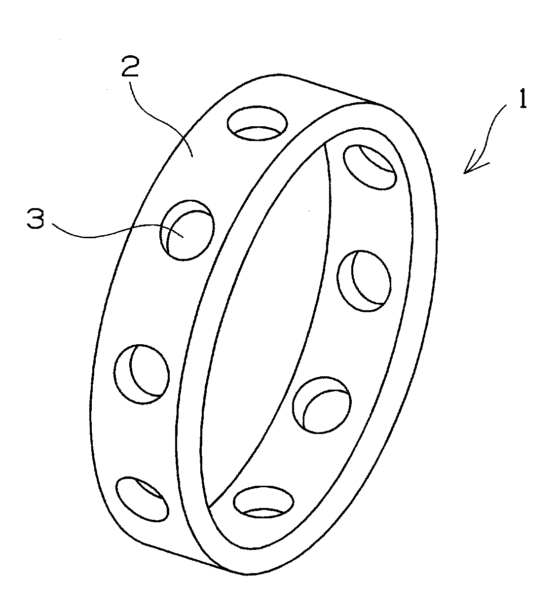
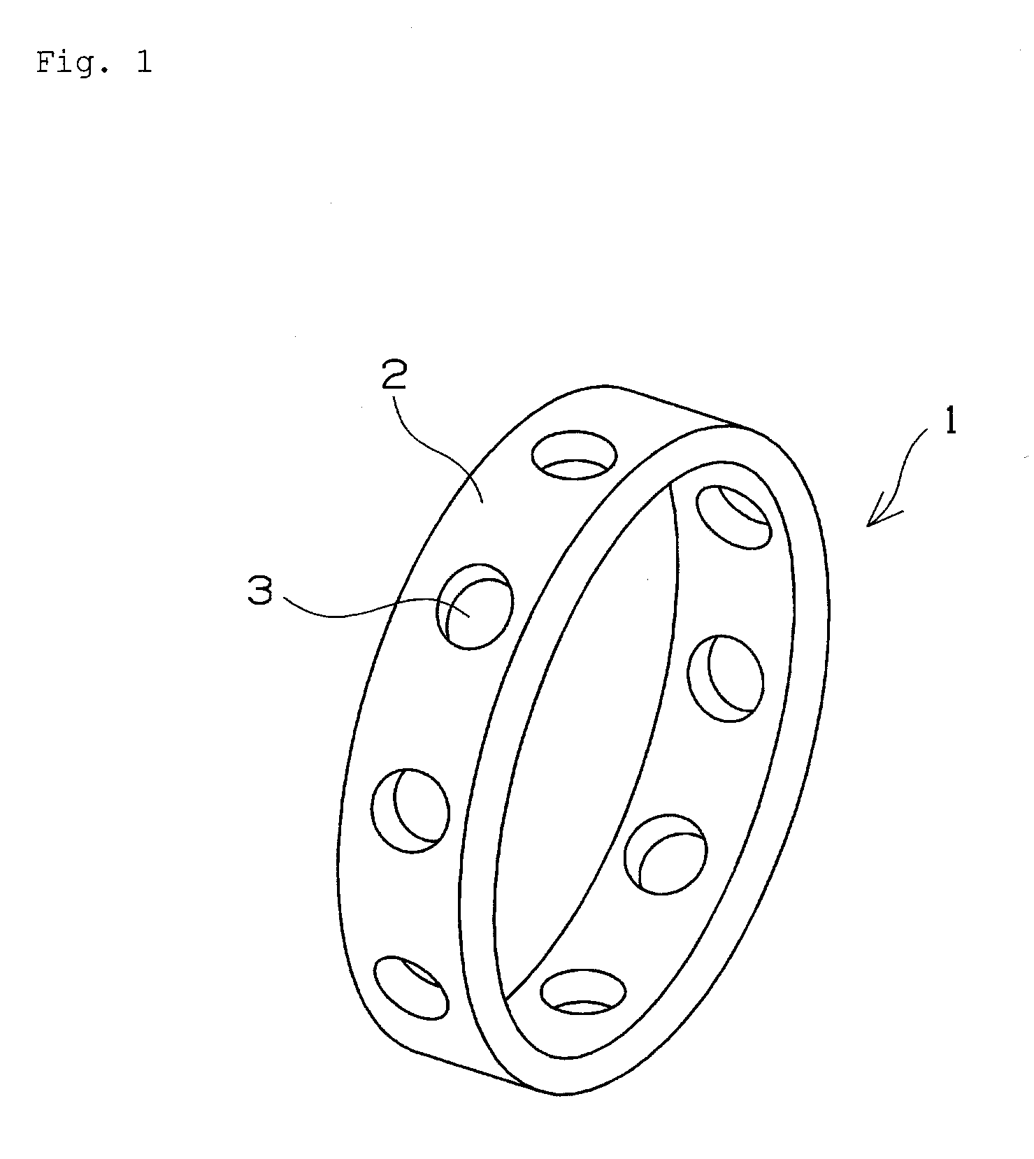
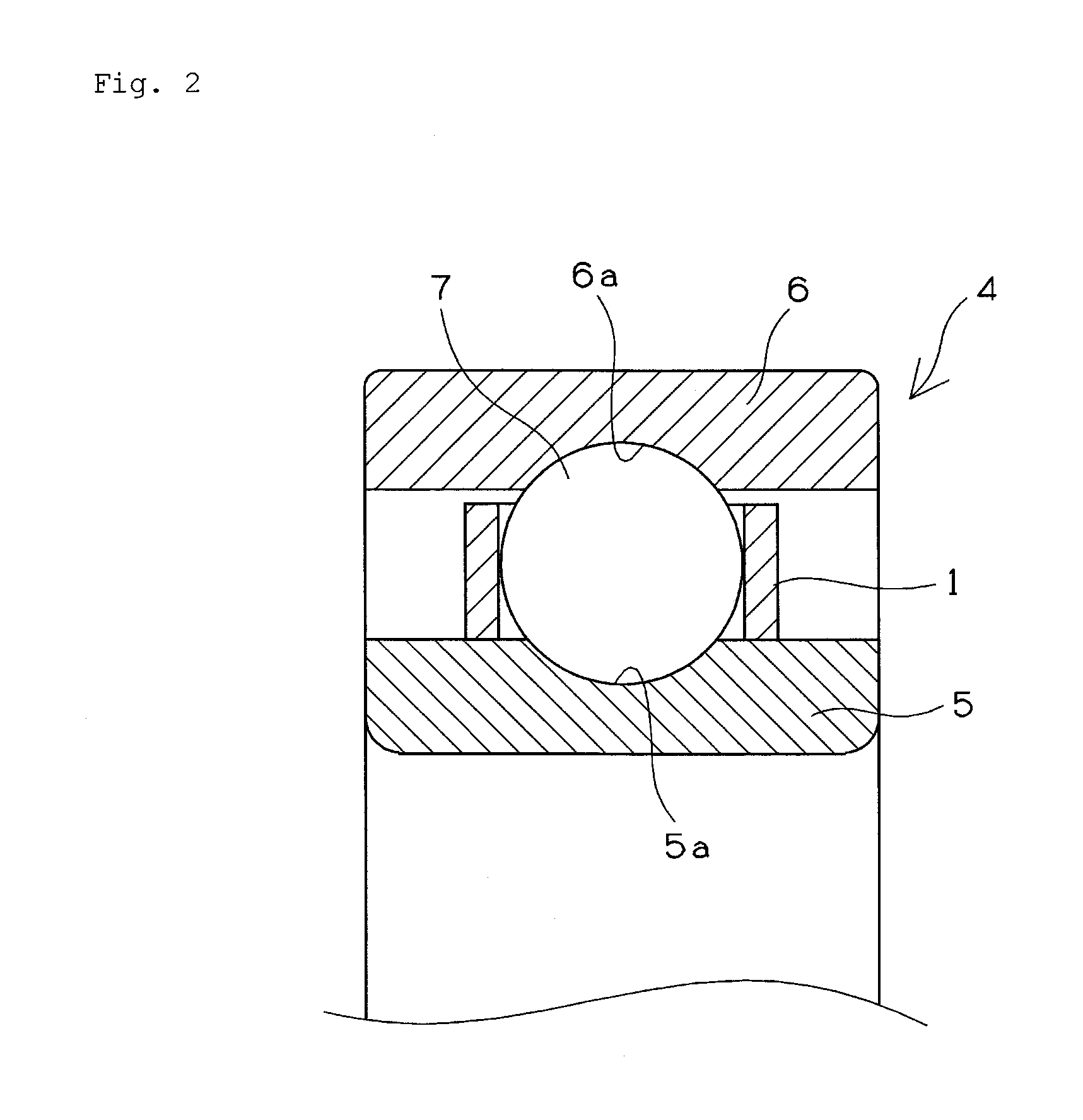
It is an object of the present invention to provide a rolling bearing which can be used in conditions in which a DN value is not less than 1,500,000 and an operating temperature is not less than 200° C. and which can be securely operated for a sufficiently long period of time without seizing, even though the rolling bearing is used in a dry run state and a cage for the rolling bearing. A cage (1) is formed by molding a carbon fiber composite material composed of a matrix consisting of a high-molecular compound reinforced with a carbon fiber material. The carbon fiber material consists of a bundle of 1000 to 5000 monofilaments, a woven cloth or a unidirectional material consisting of the bundle of the monofilaments. The high-molecular compound is polyimide resin or the like whose glass transition temperature is not less than 200° C. after the high-molecular compound thermally hardens.
Description
TECHNICAL FIELD[0001]The present invention relates to a resin cage for a rolling bearing and the rolling bearing which incorporates the cage and is used in conditions in which it is operated at a high speed and a high temperature. More particularly, the present invention relates to a rolling bearing, for an airplane, which is used by rotating it at a high speed in a dry run state.BACKGROUND ART[0002]Each part of a jet engine of an airplane is demanded to be lightweight to a very high extent to improve the fuel cost thereof. For example, a cage for a bearing which is used for parts such as the main shaft of the jet engine rotating at a high temperature and a high speed is demanded to be altered from a metallic cage to a resin cage. But it is difficult to use the resin cage for a rolling bearing for the main shaft of the jet engine which is used in conditions in which a DN value is not less than 1,500,000 and an operating temperature is not less than 200° C.[0003]As a cage which is us...
Claims
Application Information
Patent Timeline
Application Date:The date an application was filed.
Publication Date:The date a patent or application was officially published.
First Publication Date:The earliest publication date of a patent with the same application number.
Issue Date:Publication date of the patent grant document.
PCT Entry Date:The Entry date of PCT National Phase.
Estimated Expiry Date:The statutory expiry date of a patent right according to the Patent Law, and it is the longest term of protection that the patent right can achieve without the termination of the patent right due to other reasons(Term extension factor has been taken into account ).
Invalid Date:Actual expiry date is based on effective date or publication date of legal transaction data of invalid patent.

