Silicon-containing block co-polymers, methods for synthesis and use
a technology of co-polymers and silicon-containing blocks, applied in the field of heteropolymer or copolymer, can solve the problems of prohibitive cost of electron beam lithography and resolution limits of optical lithography, and achieve the effect of high vapor pressur
- Summary
- Abstract
- Description
- Claims
- Application Information
AI Technical Summary
Benefits of technology
Problems solved by technology
Method used
Image
Examples
example 1
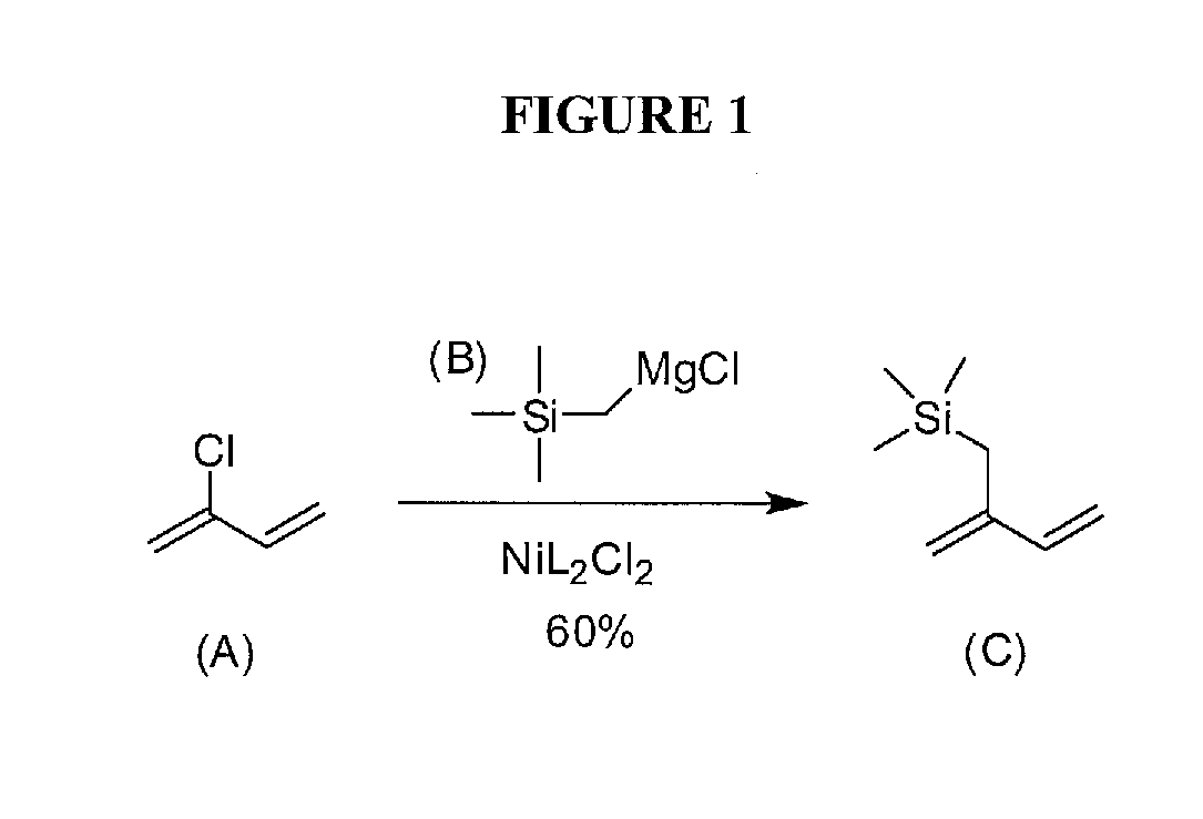
[0054]Monomer (TMSI). In a modification of a procedure from Sakurai [13], a 250 mL RBF with condenser was charged with freshly ground Mg turnings (2.2 g, 92.2 mmol), a catalytic amount of dibromoethane, diethyl ether (100 mL), and a stir bar. After stirring for 15 min at rt, the reaction mixture was brought to reflux, and chloromethyltrimethylsilane (10.6 mL, 76.8 mmol) was added drop-wise over 30 min. In a separate 1 L Round bottom flask (RBF) with addition funnel, a mixture of 1,3-bis(diphenylphosphino)propane nickel (II) chloride (1.3 g, 2.3 mmol), freshly distilled chloroprene (9.0 mL, 97.6 mmol, bp=58-61° C., 760 torr), and diethyl ether (500 mL) was stirred at 0° C. After nearly complete Mg consumption (2 h), the pale-gray Grignard solution was cooled, added drop-wise to the dark-red, chloroprene mixture over 30 min and stirred overnight at room temperature (rt). The yellow solution was quenched with H2O (500 mL) and extracted with ether (3×250 mL); the organic layers were com...
example 2
Synthesis of PS-b-PTMSI
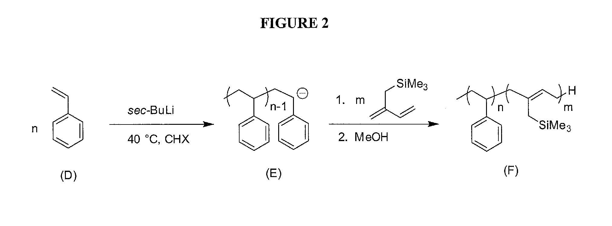
[0057]Due to the problems associated with styrene derivatives, monomer trimethyl(2-methylenebut-3-enyl)silane was synthesized. After purification over nBuLi, isoprene trimethyl(2-methylenebut-3-enyl)silane was successfully added on to a living polystyrene (PS) anion in cyclohexane (FIG. 2). 1H-NMR analysis showed a mol ratio of 83:17 Sty:TMSI (FIG. 4). Using the density of PS previously reported in the literature [11], and assuming the density of PTMSI is similar to that of polyisoprene (PI), the volume fraction of PS is approximated at 0.77. Small changes in the density of PTMSI produce relatively small changes in the volume fraction of PTMSI. According to existing literature 43, P(S-b-I) with fPI=0.24 produces cylinders of PI, therefore a cylindrical morphology is expected. GPC determined the PDI of the PS aliquot and PS-b-PTMSI to be 1.00 and 1.02, respectively with a total Mn of 65.7 kDa (FIG. 3). DSC traces of the polymer showed two Tgs (FIG. 5): one at 1...
example 3
Synthesis of Trimethyl-(2-methylene-but-3-enyl)silane
[0058]In a modified procedure from Sakurai [13], a 250 mL RBF with condenser was charged with freshly ground Mg (2.2 g, 92.2 mmol), a catalytic amount of dibromoethane, diethyl ether (100 mL), and a stir bar. After stirring for 15 min at rt, the reaction mixture was brought to reflux, and chloromethyltrimethylsilane (10.6 mL, 76.8 mmol) was added drop-wise over 30 min. In a separate 1 L RBF with addition funnel, a mixture of 1,3-Bis(diphenylphosphino)propane nickel (II) chloride (1.3 g, 2.3 mmol), freshly distilled chloroprene (9.0 mL, 97.6 mmol, bp=58-61° C., 760 ton), and diethyl ether (500 mL) was stirred at 0° C. After nearly complete Mg consumption (2 h), the pale-gray Grignard solution was cooled, added drop-wise to the dark-red, chloroprene mixture over 30 min, and stirred overnight at rt. The yellow product was quenched with H2O (500 mL) and extracted with ether (3×250 mL); the organic layers were combined, dried over MgSO...
PUM
| Property | Measurement | Unit |
|---|---|---|
| size | aaaaa | aaaaa |
| size | aaaaa | aaaaa |
| temperature | aaaaa | aaaaa |
Abstract
Description
Claims
Application Information
 - R&D
- Intellectual Property
- Life Sciences
- Materials
- Tech Scout
- Unparalleled Data Quality
- Higher Quality Content
- 60% Fewer Hallucinations
Browse by: Latest US Patents, China's latest patents, Technical Efficacy Thesaurus, Application Domain, Technology Topic, Popular Technical Reports.
© 2025 PatSnap. All rights reserved.Legal|Privacy policy|Modern Slavery Act Transparency Statement|Sitemap|About US| Contact US: help@patsnap.com


