Controlled gravity feeding czochralski apparatus with on the way melting raw material

a technology of raw material and gravity feeding, which is applied in the direction of single crystal growth, polycrystalline material growth, eutectic material solidification, etc., can solve the problems of limited possibility of providing an adequate amount of overheating, inability to obtain axially symmetric thermal fields in the melt and growing crystal, and incomplete melting of raw material fed to annular spa

Inactive Publication Date: 2013-08-29
LGS INNOVATIONS
View PDF8 Cites 23 Cited by
  • Summary
  • Abstract
  • Description
  • Claims
  • Application Information

AI Technical Summary

Benefits of technology

[0027]The principal object of the present invention which has been made to solve above-mentioned problems, is to provide a method and equipment which is able to perform outside the housing of the growth furnace continuous fast melting of raw material just after discharging it from feeder in a particle or powder form and immediate conveying this melted raw material by gravity, without any accumulation, to the crucible from which a single crystal is pulled.

Problems solved by technology

The disadvantage of these apparatus consist in that an axially symmetric thermal fields in the melt and in the growing crystal cannot be obtained because of lack of axial symmetry of the crucible and impossibility of crucible rotation.
The main disadvantages of the apparatus described in U.S. Pat. Nos. 2,892,739 and 5,314,667 result from a limited possibility of providing an adequate amount of overheating of the melt in the annular space of the crucible.
Failure to comply with this requirement would result in incomplete melting of raw material fed to annular space.
Because of a strong influence of the melt temperature in the annular space on the melt temperature in the inner space, this requirement either cannot be complied with at all or it may be met in the above described apparatus with substantial limitations, that is for certain performance parameters only (for example, for lower growth rates or smaller crystal diameters).
Moreover, heat radiation loss from the upper end of partition, extending over the melt surface, can result in the occurrence of solidification of the melt on partition's walls.
Once solidification starts on the inner wall of partition, solidified material grows toward crystal until touching it, thus interrupting the crystal growing operation.
Another disadvantage of the apparatus described in U.S. Pat. Nos. 2,892,739 and 5,314,667 resides in that outgrows may appear on the walls of annular space because of crystallization on the walls of liquid drops arising from splashes making by raw material particles hitting the melt surface, as well as due to direct incidence of these particles on the walls and their sticking to them.
Gradual increase in the outgrows size sooner or later results in complete obturation of the radial gap in the annular space of the crucible, hence in the interruption of replenishing the melt with raw material and interruption of continuous growing process.
Additional problem arises when these apparatus are used for growing crystals, which density in a solid form is less than in a liquid form, as in the case of silicon, for example.
Any or all above means aimed at preventing solidification of the melt on partition or crucible walls and at providing the entire melting of raw material particles, falling into the annular space of the crucible, may, of course, enhance the continuous growing process, but they don't eliminate the main cause of all mentioned above disadvantages: strong influence of the melt temperature in the annular space on the melt temperature in the inner space, or, in other words, zones of melting raw material and of growing single crystal are too close to each other.
These means also unlikely may be universal, because in case of growing crystals of substances which melt has high vapor pressure (e.g. alkali halides) the condensation of vapors on shields and covers may disturb their normal functioning as well as may cause the accumulation of condensate and its subsequent falling into the melt.
This kind of feed maintenance, strictly speaking, is not continuous and, because of alternating solidification and melting raw material in the capillary, can have some restrictions in respect of frequency of discrete feedings, which in some cases can be not high enough to be consistent with really continuous crystal growth.
But the main disadvantage of the described apparatus is the lack of axial symmetry of the thermal field around the single crystal being pulled, caused by additional crucible with its heaters.
Disadvantages of this kind of recharging melted raw material may result from difficulties to create a reliable seal between walls of housings and incandescent feeding tube (heated above the melting point of raw material), what needs to be done both to provide a reliable control of the feeding rate and to prevent contamination of the melt due to air leaks when the growing is conducted at low pressures.
The apparatus does not use any partition between the growing crystal and the immersed end of siphon tube, and this is its obvious disadvantage, because the hotter molten raw material, supplied by heated to high temperatures siphon tube, may easily reach the perimeter of growing crystal and cause its partial melting.
Besides, the lack of partition imposes a limitation on the rotation rate of the main crucible, because at high rotation speed some waves or ripples on the surface of the melt, arising from immersed end of the siphon tube, can reach the growing crystal and degrade its quality.
Nevertheless the apparatus under consideration is not free of disadvantages.
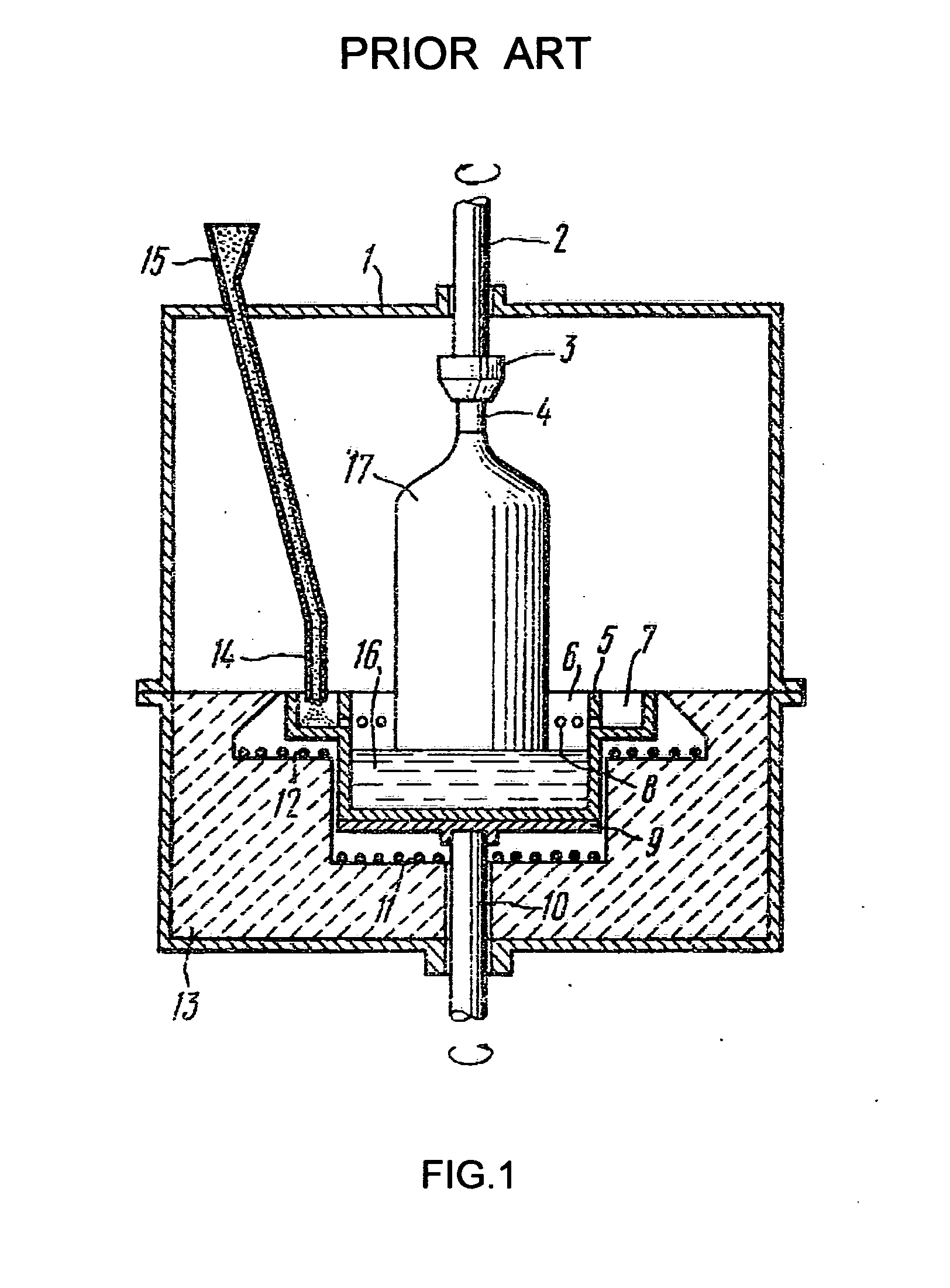
The main disadvantage lies in the fact that the radiant heat exchange between the hottest lower part of growing crystal 17 and the cold walls of housing 1 is shielded by the inner walls of outer container 7 rising above the melt level.
This makes difficult to remove the heat of fusion and forces to lower the temperature of melt 16 closer to the melting point resulting in limitation of growth rate, especially on the early stage of growing in length when the height of the crystal is less than the distance between the melt level and the upper end face of crucible 5.
Another disadvantage comes from the fact that side heater 12 is located too close to the column of melt 16, and because of this there is definite limitation of its maximal allowable temperature resulting in restriction of the rate of melting raw material particles on the bottom of outer container 7, that is in restriction of the feeding rate.
One more disadvantage of the apparatus described in U.S. Pat. No. 4,203,951 is the lack of partition between the inner walls of crucible and the growing crystal; if the temperature of the melt flowing down from apertures 8 is substantially higher than the temperature of the bulk melt, the growing crystal may be partially melted at its perimeter.

Method used


Image

  • Controlled gravity feeding czochralski apparatus with on the way melting raw material
  • Controlled gravity feeding czochralski apparatus with on the way melting raw material
  • Controlled gravity feeding czochralski apparatus with on the way melting raw material

Examples


Embodiment Construction

[0036]FIG. 2 is a schematic sectional view of the apparatus for continuous growing single crystals by Czochralski method according to the present invention. The apparatus comprises a growth furnace housing 1, a vertical crystal-pulling rod 2 provided with a holder 3 for a seed crystal 4, a crucible 5 which is mounted on a support 6 rigidly secured to a vertical rod 7. A bottom heater 8 is disposed under the support 6, and an annular heater 9 surrounds the upper part of the crucible 5, being located just under its inclined flange 10. The apparatus also comprises means (not shown) for rotation and reciprocation of the rod 2 and for rotation of the rod 7. Both rods are inserted vacuum-tightly into the housing 1. A housing 11 of a melting furnace, which is intended for continuous melting of raw material, is mounted adjacent housing 1 and is connected to it vacuum-tightly, forming a united hermetic volume. The melting furnace comprises a cylindrical heater 12 and located inside it a cyli...


PUM

PropertyMeasurementUnit
thermal energyaaaaaaaaaa
temperatureaaaaaaaaaa
melting pointaaaaaaaaaa

Abstract

A melting furnace is mounted adjacent a growth furnace in which a single crystal ingot is pulled from the melt according to the Czochralski method. The melting furnace comprises a receiving container for melting therein raw material in a particle or powder form falling in it from a feeder. The receiving container accommodates a set of slope-wise plates providing a distributed sliding of partially melted raw material particles over the surface of these plates and their complete melting while moving downward; eventually the melted raw material flows into the crucible of the growth furnace through a heated conveying tube extending slantingly from the conical bottom of the receiving container to the crucible through coaxial openings in housings of both furnaces. The rate of feeding is defined solely by a feeder, and at continuous feeding the raw material flows continuously by gravity from the feeder to the crucible of the growth furnace, first in a solid state (powder, granules, pellets, etc.) and then in a liquid state.

Description

U.S. PATENT DOCUMENTS[0001]2,892,739June 1959Rusler117 / 9323,507,625April 1970Deyris117 / 334,036,595July 1977Lorenzini et al.117 / 2024,203,951May 1980Goriletsky et al.117 / 2144,282,184August 1981Fiegl et al.117 / 2024,547,258October 1985Witter et al.117 / 334,659,421April 1987Jewett117 / 305,087,321February 1992Kamio et al.117 / 315,087,429February 1992Kamio et al.117 / 2135,126,114June 1992Kamio et al.117 / 2135,139,750August 1992Shima et al.117 / 2135,143,704September 1992Nakahama et al.117 / 2135,242,531September 1993Klingshirn et al.117 / 9325,270,020December 1993Suzuki et al.117 / 315,290,395March 1994Matsumoto et al.117 / 185,314,667May 1994Lim et al.117 / 315,324,488June 1994Klingshirn et al.117 / 9325,360,480November 1994Altekruger117 / 2145,462,011October 1995Tomzig et al.117 / 185,580,171December 1996Lim et al.117 / 2135,820,649October 1998Ogure et al.117 / 336,231,669May 2001Altekruger et al.117 / 214OTHER PUBLICATIONS[0002]V. I. Goriletsky et al., “Automated pulling of alkali halide single crystals”, Journal o...

Claims


Application Information

Patent Timeline
Patent Type & Authority Applications(United States)
IPC IPC(8): C30B15/02C30B15/00
CPCY10T117/1052Y10T117/1032Y10T117/1068C30B15/002Y10T117/1056Y10T117/10Y10T117/1008Y10T117/1004Y10T117/1024C30B15/02
Inventor EIDELMAN, LEV GEORGEZHELEZNYAK, VLADIMIR ILYA
Owner LGS INNOVATIONS
Why Eureka
Try Eureka