
Method for manufacturing pneumatic tire

Inactive Publication Date: 2013-08-29
SUMITOMO RUBBER IND LTD
View PDF9 Cites 6 Cited by
  • Summary
  • Abstract
  • Description
  • Claims
  • Application Information

AI Technical Summary

Benefits of technology

The present invention relates to a tire structure with a layered inner liner that has a reduced thickness step difference at the joints between the inner liner and the unvulcanized rubber sheet. The joints are formed at positions apart from each other in the circumferential direction of the drum, which prevents peeling off of the joints due to remaining air. The inner liner is made of a composite layer of a thermoplastic elastomer and an SIBS material, which enhances the adhesive strength with the adjacent carcass ply and has a high reinforcing effect when the joints peel off. This reduces damage and breakage of the product tire.

Problems solved by technology

In addition, since the end portions of laminate P form the joint at one location on the circumference of drum 5A in this technique, peeling-off of the joint of the inner liner of the molded green tire may cause a damage to an adjacent carcass ply.
However, the material, which is thinner and has a higher air permeation resistance than an inner liner made of butyl-based rubber, is inferior to the inner liner made of butyl-based rubber in vulcanization adhesive strength with insulation rubber and carcass ply rubber adjacent to the inner liner.
In particular, if the joint of the inner liner has a weak adhesive strength, the joint may peel off during driving, which may cause a reduction in the internal pressure of the tire, and burst of the tire.
Further, since the joint has a structure in which another member is exposed inside, an air leakage path may be formed, and a reduction in the internal pressure of the tire is likely to be caused.
However, in order to displace the both ends in the extending direction from each other, it is necessary to cut each member one by one to have a constant size, and individually bond the members with being displaced from each other, which may deteriorate productivity.
Further, depending on the bonding method, accuracy is deteriorated and air remains between the films, which may cause a damage during vulcanization of the tire.

Method used


Image

  • Method for manufacturing pneumatic tire
  • Method for manufacturing pneumatic tire
  • Method for manufacturing pneumatic tire

Examples


embodiment 1

[0037]

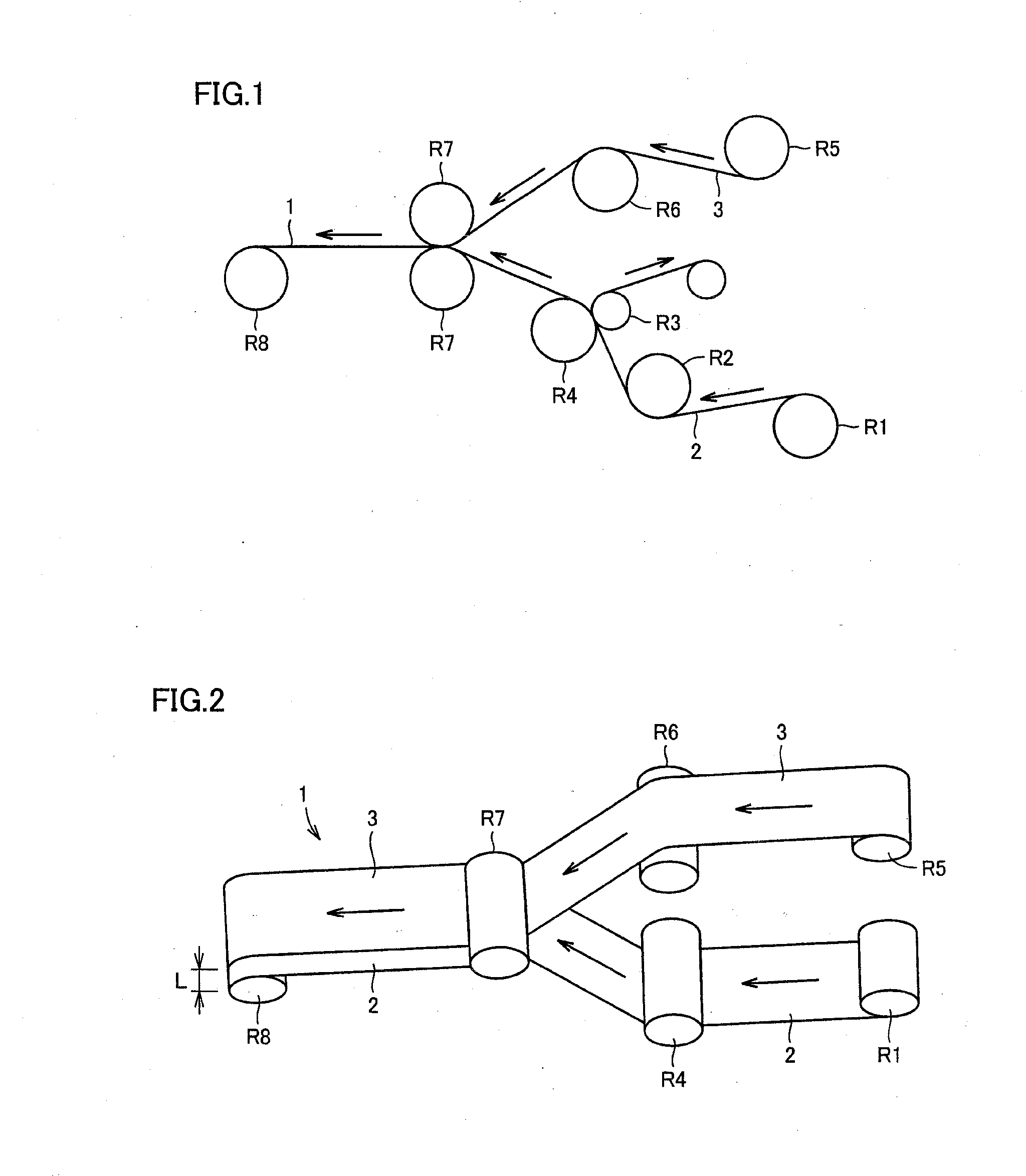
[0038]FIG. 1 is a schematic lateral view showing the assembly step, and FIG. 2 is a schematic perspective view showing the assembly step. In FIGS. 1 and 2, a film-like inner liner 2 covered with exfoliate paper is fed from a storage roll R1 via a first drive roller R2 in a direction indicated by an arrow, and is separated from the exfoliate paper at peel-off rollers R3, R4. Then, inner liner 2 is fed to a pair of calender rolls R7.

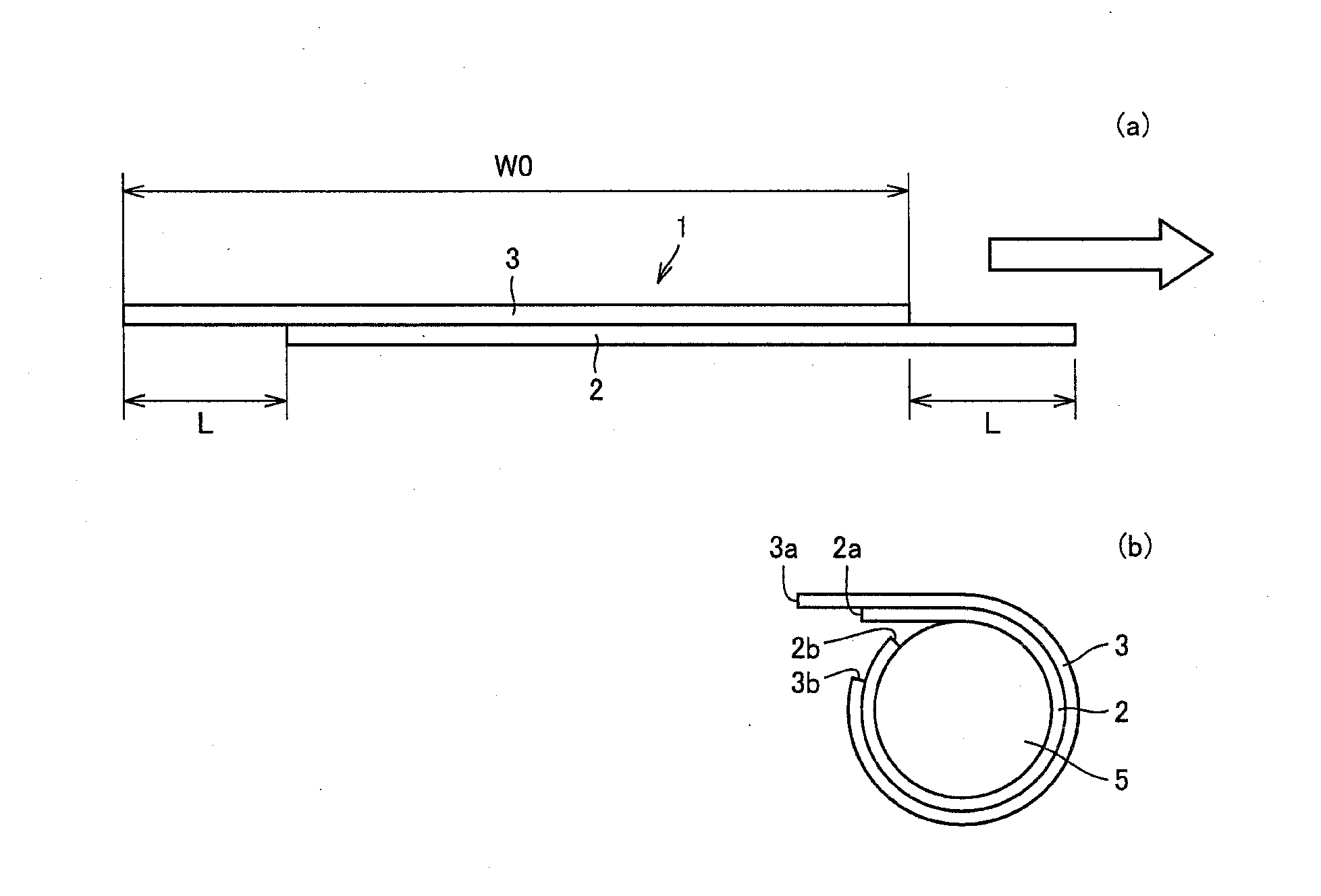
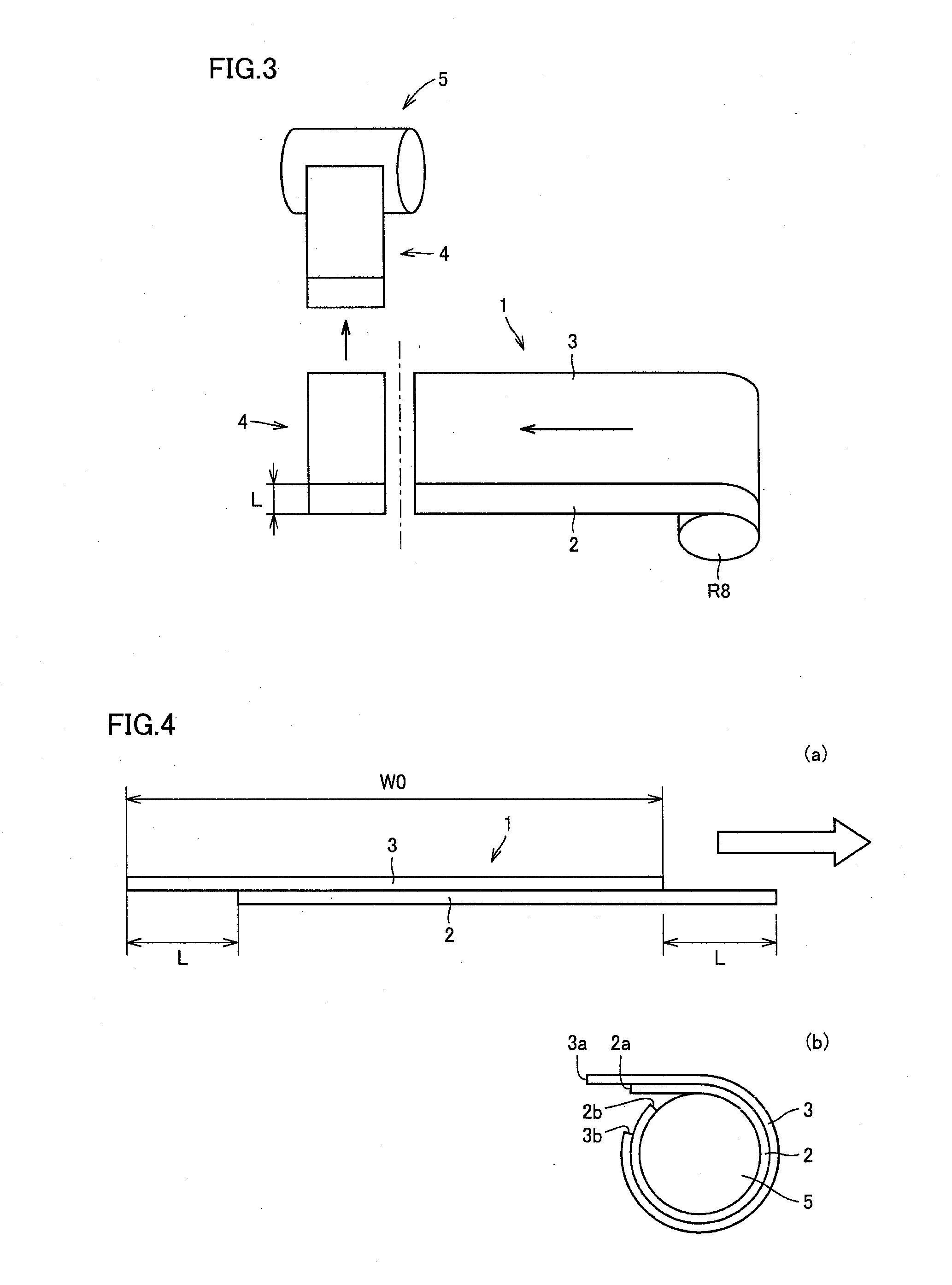
[0039]On the other hand, an unvulcanized rubber sheet 3 is fed via a second drive roller R6 to the pair of calender rolls R7. Inner liner 2 and unvulcanized rubber sheet 3 are bonded there to manufacture a laminate 1. Laminate 1 is taken up by a take-up roll R8 for temporary storage, or is continuously fed to the subsequent cutting step. Here, inner liner 2 and unvulcanized rubber sheet 3 having a substantially identical width are used, and positions of their both ends are displaced from each other to form a distance L.

[0040]Here, displaced distance ...

embodiment 2

[0049]Although inner liner 2 and unvulcanized rubber sheet 3 having an identical width are used in Embodiment 1, inner liner 2 in the present embodiment has a width W2 formed to be larger than a width W1 of unvulcanized rubber sheet 3.

[0050]FIG. 5 is a schematic view showing the cutting step. Laminate 1 is fed from take-up roll R8, or continuously from the assembly step, to a cutter by a belt conveyer. Laminate 1 is cut to have a predetermined length in the longitudinal direction in accordance with the size of the tire to manufacture cut sheet 4. A conventional technique such as cutting with a knife can be adopted to cut the laminate. The cutting direction of cut sheet 4 corresponds to the circumferential direction of the drum, and the cutting length thereof in the longitudinal direction corresponds to the width direction of drum 5.

[0051]FIG. 6(a) is a cross sectional view of the laminate, and FIG. 6(b) is a schematic view showing the state where the laminate is wound on the drum. H...

examples

[0088]

[0089]The styrene-based thermoplastic elastomers (SIB, SIBS, and SIS) used to manufacture the polymer laminate composed of the first layer and the second layer used as the inner liner in accordance with the present invention were prepared as described below.

[0090][SIB]

[0091]In a 2 L reaction vessel equipped with a stirrer, 589 mL of methylcyclohexane (dried over molecular sieves), 613 mL of n-butyl chloride (dried over molecular sieves), and 0.550 g of cumyl chloride were charged. After cooling the reaction vessel to −70° C., 0.35 mL of α-picoline (2-methylpyridine) and 179 mL of isobutylene were added. Further, 9.4 mL of titanium tetrachloride was added to start polymerization, and then the solution was reacted for 2.0 hours while being stirred at −70° C. Next, 59 mL of styrene was added into the reaction vessel and the reaction was continued for another 60 minutes, and then the reaction was terminated by adding a large amount of methanol. After removing the solvent and the l...


PUM


Abstract

A method for manufacturing a pneumatic tire including: (a) an assembly step of bonding the inner liner and an unvulcanized rubber sheet with end portions thereof in a width direction being displaced from each other in the range of 50 mm to 500 mm in the width direction to manufacture a laminate; (b) a cutting step of cutting the laminate to have a constant length corresponding to a width of a drum to manufacture a cut sheet; and (c) a joining step of winding the cut sheet on entire circumference of the drum such that a cut surface thereof extends in a circumferential direction of the drum and the inner liner is disposed on an inner surface side, and joining the end portions of the inner liner and joining the end portions of the unvulcanized rubber sheet.

Description

TECHNICAL FIELD[0001]The present invention relates to a method for manufacturing a pneumatic tire, in particular to a method for molding an inner liner, and to a method for manufacturing a pneumatic tire including the step of molding a green tire by manufacturing a laminate of an inner liner and an unvulcanized rubber sheet such as a carcass ply.BACKGROUND ART[0002]Recently, weight saving of tires has been pursued because of strong social demands for fuel efficiency of automobiles. Of tire members, weight saving has also been required for an inner liner serving as an air shutoff layer, which is disposed inside a tire and is required to reduce leakage of air from the inside to the outside of a pneumatic tire.[0003]At present, for a rubber composition for the air shutoff layer, rubber formulation mainly composed of butyl rubber which contains, for example, 70 to 100% by mass of butyl rubber and 30 to 0% by mass of natural rubber is used to improve air permeation resistance of the tire...

Claims


Application Information

Patent Timeline
IPC IPC(8): B29D30/30
CPCB29D30/3007B29D30/46B29D30/30B60C1/0008B60C2005/145B29D2030/0682B29D2030/3085B60C5/04B60C5/14B60C9/04
Inventor SUGIMOTO, MUTSUKI
Owner SUMITOMO RUBBER IND LTD
Learn More