Physical process for the recovery of iron from magnetic cementitious spherical particles generated from metallurgical byproducts

a technology of physical processes, which is applied in the field of physical processes for the recovery of iron from magnetic cementitious spherical particles generated from metallurgical byproducts, can solve the problems of low throughput rate, limited amount of slag that can be used in this process, and inability to use magnetic iron in any application, so as to facilitate the transportation of compacted materials

Inactive Publication Date: 2013-10-24
APLICADA CENT DE INVESTIGACIO
View PDF8 Cites 3 Cited by
  • Summary
  • Abstract
  • Description
  • Claims
  • Application Information

AI Technical Summary

Benefits of technology

[0004]The present invention shows a new process resulting from the application MX/a/2011/013658, which includes the projection assisted by argon (Ar)/helium (He) plasma of different iron-rich powder precursors, which are common byproducts of various industrial metallurgical activities. Iron contained in this type of industrial byproducts is generally found as iron oxide, typically wustite (FeO), a non-magnetic phase, and also present in a minor proportion as a mixture of other iron oxides. Specifically, the present invention uses slag resulting from the steel process of the basic oxygen furnace (B.O.F.). The slag i

Problems solved by technology

However, in some cases the high content of phosphorus limits the amount of slag that can be used in this process.
Currently, this involves low throughput rates due to the reuse of only 25% of the produced slag [Deyong Wang, Maofa Jiang, Chengjun Liu, Yi Min, Yuyuan Cui, Jian Liu

Method used


Image

  • Physical process for the recovery of iron from magnetic cementitious spherical particles generated from metallurgical byproducts
  • Physical process for the recovery of iron from magnetic cementitious spherical particles generated from metallurgical byproducts
  • Physical process for the recovery of iron from magnetic cementitious spherical particles generated from metallurgical byproducts

Examples


example 1

General process for the recovery of iron from magnetic cementitious spherical particles produced from the E.B.O.F.

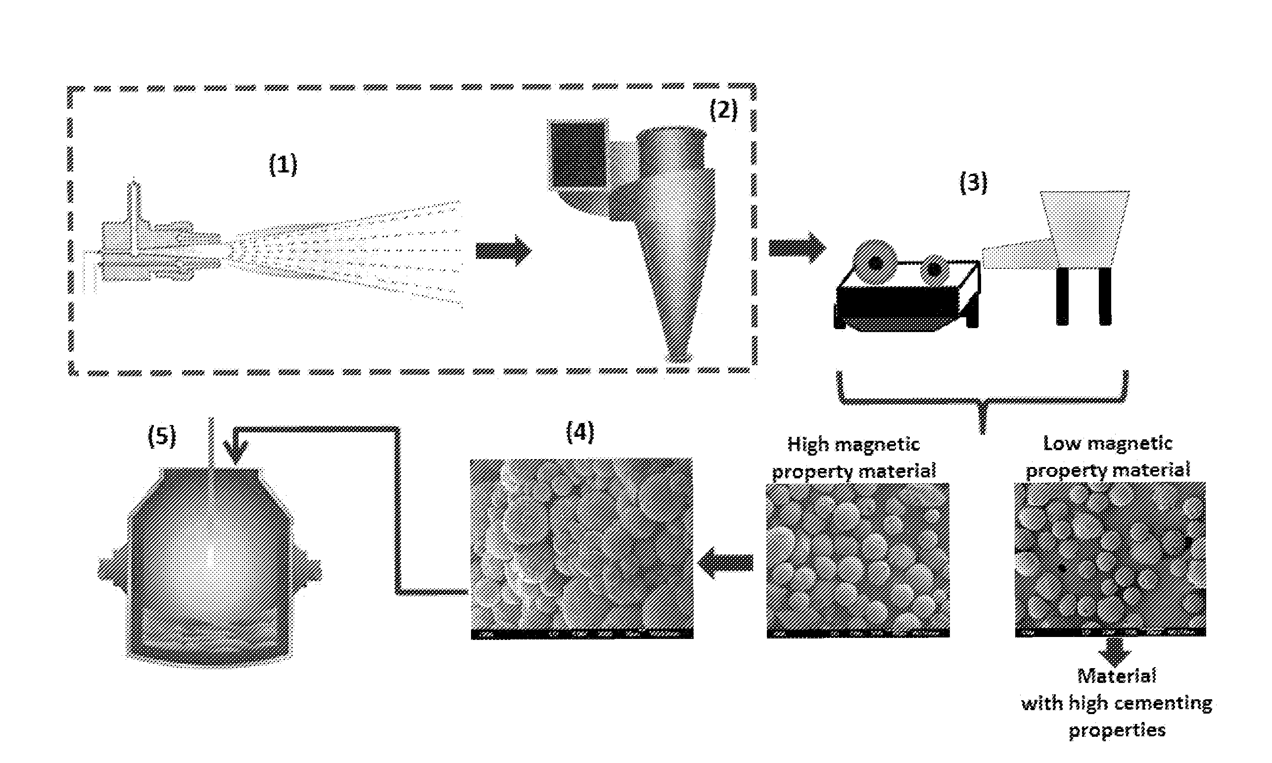
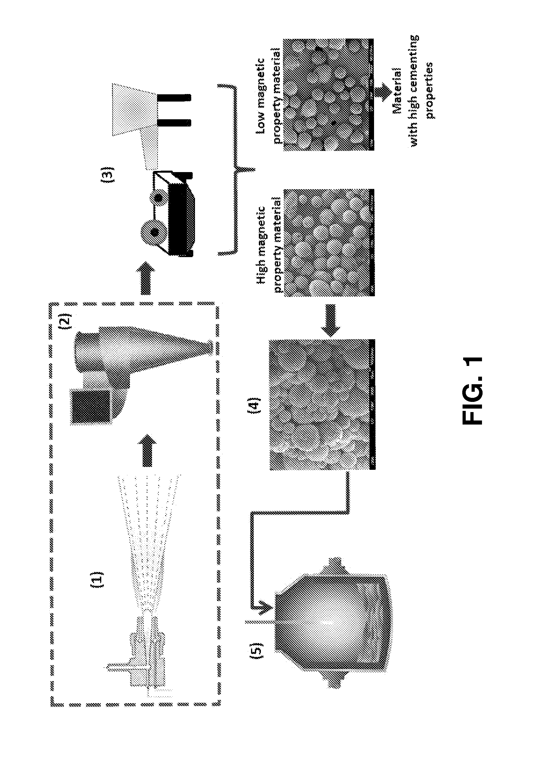
[0020]The process set forth in FIG. 1, shows a section enclosed within a dashed line box, this section corresponds to Patent Application No. MX / a / 2011 / 013658. However, once the new material, cooled off (magnetic cementitious spherical particles), leaves the collector, it passes to a magnetic separation device capable of classify the material into two or more fractions according to the applied magnetic field. Once separation is achieved, basically in two fractions: (1) an iron-rich and highly magnetic one, and (2) another cementitious fraction with practically very little or almost no magnetic properties, said highly magnetic fraction is mixed with an aqueous solution, which may or may not contain silica nanoparticles to form a magnetic aggregate. Adding silica nanoparticles promotes the chemical reaction with products generated by the hydration of the highly magnetic sph...

example 2

Characterization by X-Ray Diffraction (XRD) of the Precursor Material (B.O.F.S.) and the Separated Fraction of Highly Magnetic Spherical Particles

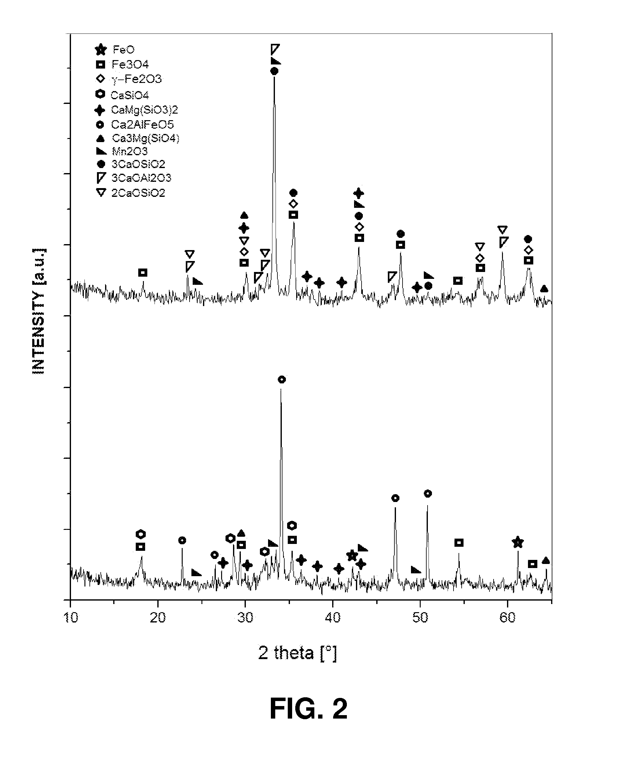
[0021]The XRD pattern of the original B.O.F.S, and the fraction of highly magnetic spherical particles, was obtained using an X-ray diffractometer, model Siemens 500, with Kα radiation of Cu (λ=1.5418 Å), at 35 kw and 25 mA. The diffractogram of FIG. 2 indicates the presence of different original crystalline phases of the B.O.F.S. (bottom XRD), such as: Wustite (FeO), Magnetite (Fe3O4), Brownmillerite (Ca2AlFeO5), Larnite (CaSiO4), Bixbyite (Mn2O3), Diopside (CaMg(SiO3)2) and Merwinite (Ca3Mg(SiO4)). On the other hand, the upper difractrogram corresponds to the fraction of highly magnetic spherical particles, and can be noticed the presence of phases such as Magnetite (Fe3O4), Maghemite (γ-Fe2O3), Mervinite (Ca3Mg(SiO4)), Bixbyite (Mn2O3), Diopside (CaMg(SiO3)2), Tricalcium Aluminate (3CaOAl2O3), Dicalcium Silicate (2CaO.SiO2) and Tricalci...

example 3

Morphology and Chemical Composition by Field Emission Scanning Electron Microscopy of the Separated Fraction of Highly Magnetic Spherical Particles

[0022]Morphological analyses of the spherical particles that form the highly magnetic fraction were performed by Field Emission Scanning Electron Microscopy, using a JEOL model JSM-7401F equipment and its respective energy dispersive X-rays spectroscopy (EDS) equipment Noran-200, to determine the semiquantitative chemical composition was performed through the analysis by EDS. FIG. 3 shows the photomicrograph of the Field Emission Scanning Electron Microscopy of the separated fraction of highly magnetic spherical particles, where the surface of the spheres, and their sphericality and roughness. Moreover, and as indicated in Table 2, all oxides present in the magnetic cementitious spherical particles remain very similar in proportion and amounts to those shown by the precursor used (B.O.F.S.) However, and about the sulfur content (reported ...


PUM

PropertyMeasurementUnit
Fractionaaaaaaaaaa
Fractionaaaaaaaaaa
Timeaaaaaaaaaa

Abstract

A physical process for recovering iron from magnetic cementitious spherical particles generated from metallurgical by-products such as slag from a basic oxygen converter (B.O.F.S) by applying a thermal process assisted by Ar—He plasma, which allows the microstructural and morphological transformation of these compounds based on iron, resulting in the generation of magnetic phases, among others. The separation process is based on the classification of the particles according to their new magnetic properties. Thus, when applying a magnetic field, the particles are separated into two fractions: a highly magnetic one and with low cementitious properties, and another fraction with high cementitious properties and almost no magnetic properties. The highly magnetic fraction is mixed with an aqueous medium to form an agglomerate and facilitate its transportation to be reefed to an iron melting process. The fraction with low magnetic properties has potential applications as a densifier in non-conventional cement and concrete.

Description

TECHNICAL FIELD OF THE INVENTION[0001]This invention relates to a process for recovering iron, more particulary a process for recovering iron from magnetic cementitious spherical particles generated from metallurgical by-products.BACKGROUND OF THE INVENTION[0002]For recovering iron from steel slags, several processes have been developed which typically include crushing of them, in one or more stages to bring them to a sinter plant, if any, or directly to the B.O.F. furnace to adjust CaO and MgO contents, and recovery of iron and magnesium. However, in some cases the high content of phosphorus limits the amount of slag that can be used in this process. Currently, this involves low throughput rates due to the reuse of only 25% of the produced slag [Deyong Wang, Maofa Jiang, Chengjun Liu, Yi Min, Yuyuan Cui, Jian Liu, and Yongcang Zhang. Enrichment of Fe-Containing Phases and Recovery of Iron and Its Oxides by Magnetic Separation from B.O.F. slags. Steel Research Int. 83 (2012) No. 2, ...

Claims


Application Information

Patent Timeline
IPC IPC(8): C21B3/00
CPCC21B3/00C21B5/008C21C5/562C21B2200/00C22B7/005C22B7/04Y02P10/20
Inventor PERERA MERCADO, YIBRAN ARGENISSAUCEDO SALAZAR, ESMERALDA MONSERRATRODRIGUEZ RUIZ, FABIAN ROBERTO
Owner APLICADA CENT DE INVESTIGACIO
Why Eureka
Try Eureka