
Surface-tension based flow guidance in a microstructure environment

a microstructure environment and surface tension technology, applied in the field of microfluidics, can solve the problems of inability to replicate the process in traditional cell culture on flat plastic, intractable manufacturing, and high toxic

Inactive Publication Date: 2013-10-31
BELLBROOK LABS
View PDF3 Cites 6 Cited by
  • Summary
  • Abstract
  • Description
  • Claims
  • Application Information

AI Technical Summary

Benefits of technology

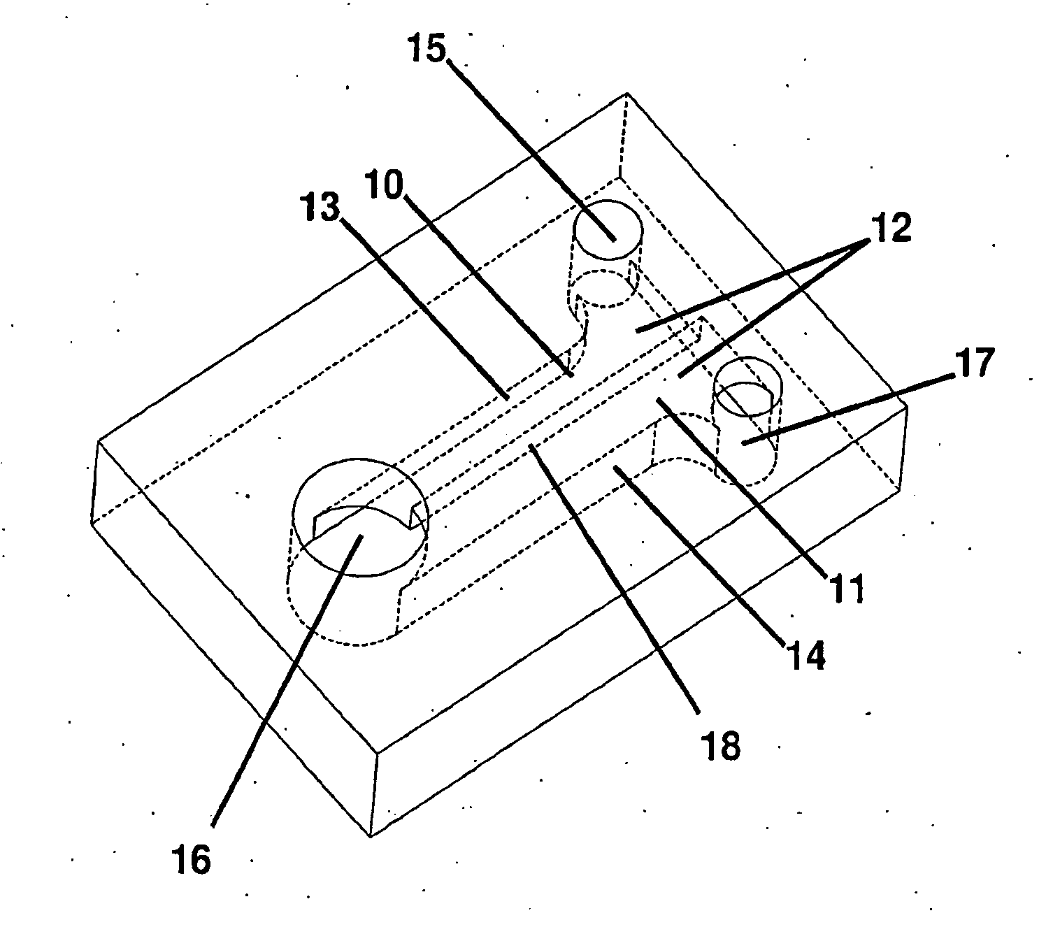
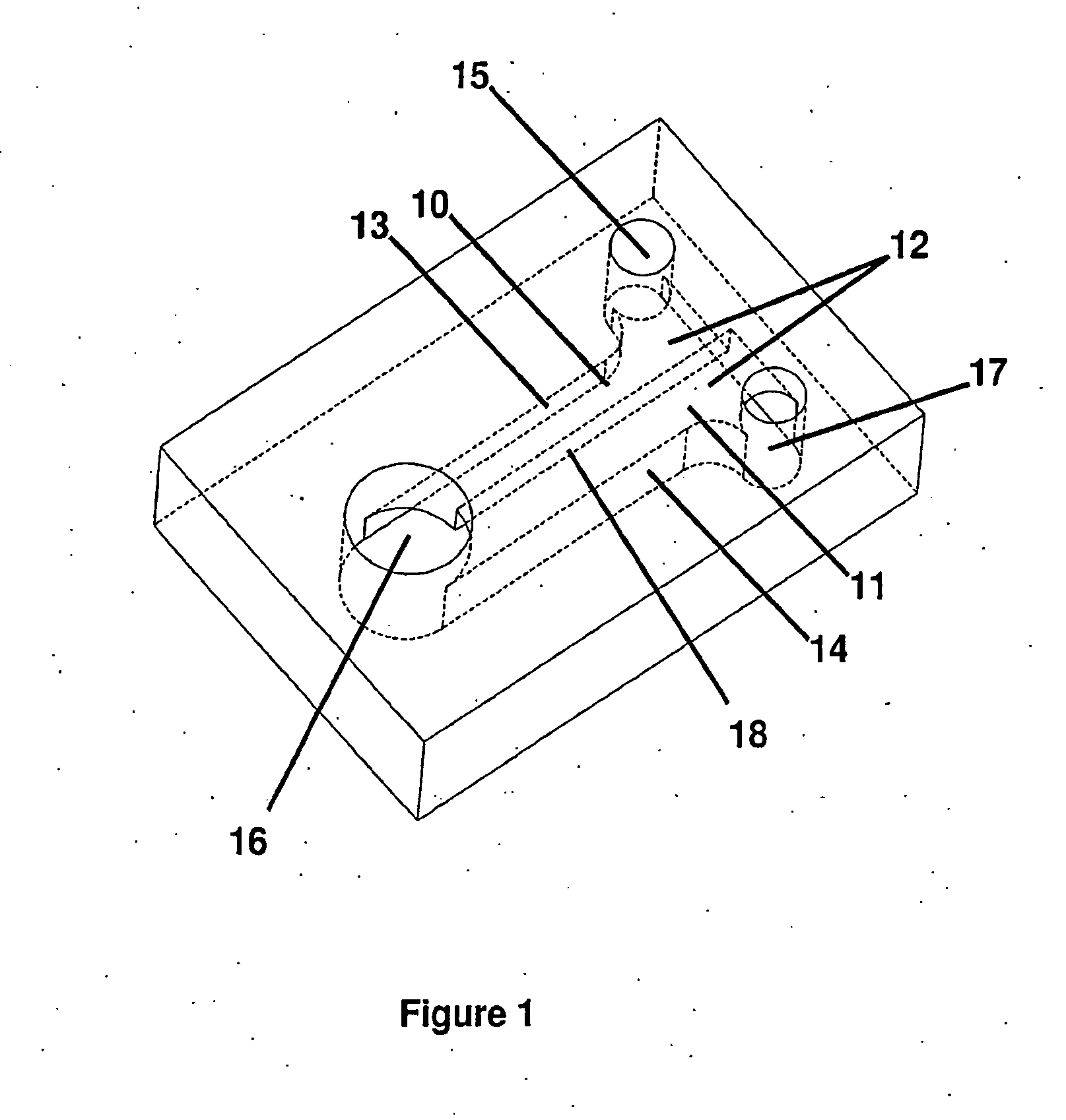
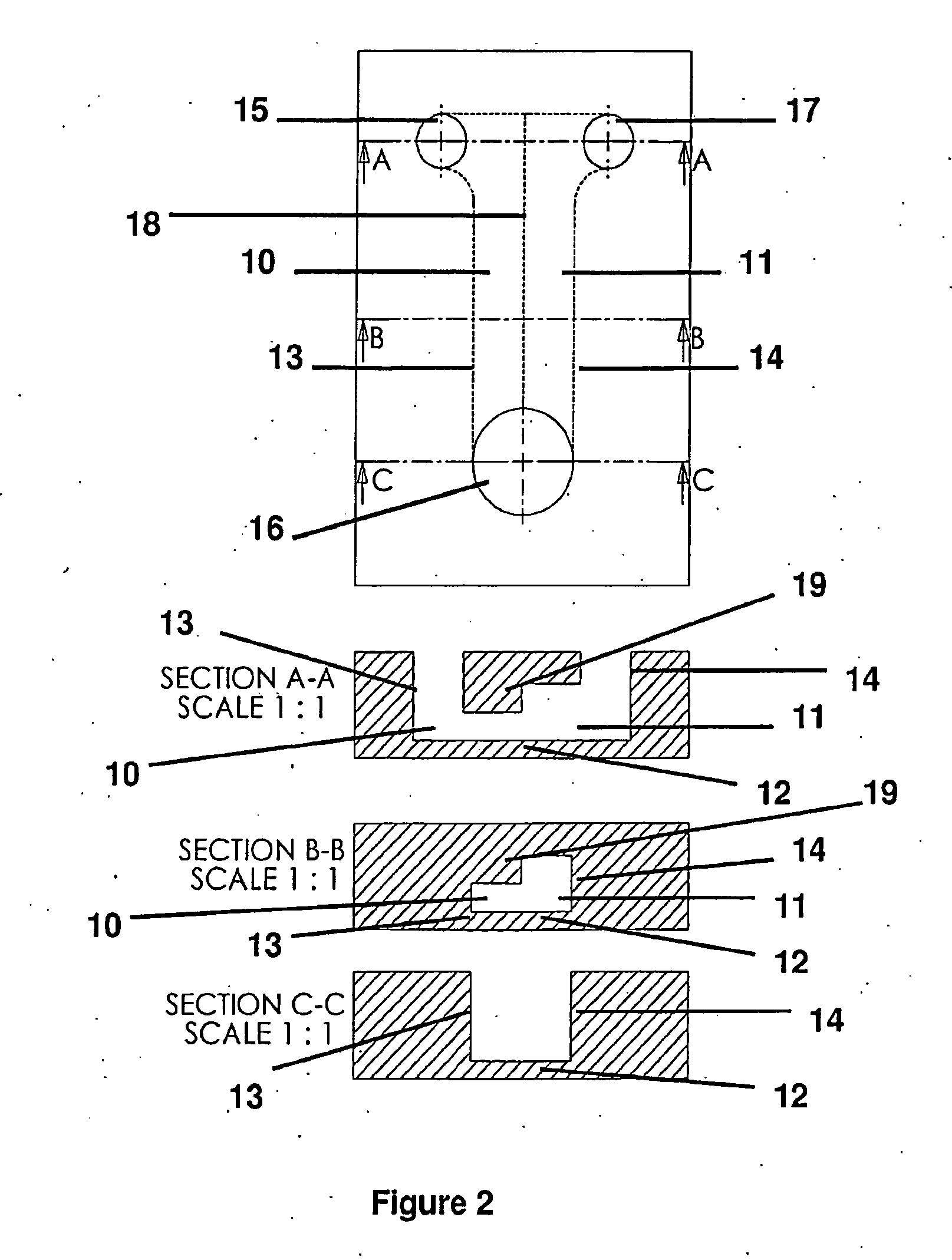
The patent describes a device and method for controlling the flow and delivery of liquids and particles using a network of hollow microstructures. The device contains regions with different geometries that affect capillary action, allowing liquids to preferentially fill one region over another. The device can be used in drug candidate analysis, chemical analysis, chromatography, flow sensors, and microprocessor chip and fuel cell manipulation and fabrication. The method involves adding liquids to the device and utilizing them in a liquid state or solidified, gelled, cross-linked, polymerized, or accumulated through gravity or centrifugation. The technical effects of this invention include improved control over liquid delivery and manipulation of materials in a micro-scale system.

Problems solved by technology

Virtual walls have been created by patterning self-assembled monolayers to define hydrophilic and hydrophobic regions to guide fluid flow (Zhao et al., 2001); however, this approach is intractable for manufacturing.
This combination of geometric and chemical pattern requires specific chemistry for photo-cross-linking, and is not compatible with sensitive biological systems, such as cultured cells, on which it tends to have significant toxic effect.
These processes cannot be replicated in traditional cell culture on flat plastic.

Method used


Image

  • Surface-tension based flow guidance in a microstructure environment
  • Surface-tension based flow guidance in a microstructure environment
  • Surface-tension based flow guidance in a microstructure environment

Examples


example 1

[0051]The device and method described here may be utilized to construct an experimental model of tumor cell invasion. In vivo, the tumor cells are initially contained within a tumor mass, but as the tumors turn malignant, the cells develop the ability to break free of the tumor mass and invade into the surrounding connective tissue. One embodiment of this application would be a microfluidic structure where the first region would be prepared to contain a gel representing the connective tissue, and the second region would be prepared to contain cells representing the tumor. Since the gel can be made such that it initially has no cells, migration, or invasion, of cells into the gel is easily detected and quantified. The process can be quantified in terms of cell number reaching beyond a certain distance inside the region, or by a statistical analysis of cell location across the population. If the gel is collagen-I, the assay will enable an analysis of tumor cell migration through conne...

example 2

[0052]Another embodiment of this application involves the construction of a biological model assay where cells are sandwiched in between two layers of an extracellular matrix gel. The purpose of doing this is to provide the cells with a three-dimensional environment in which to grow. This type of arrangement has been shown to provide significant advantages over culturing the same cells on extracellular matrix-coated, rigid plastic surfaces (Montesani et al. 1983); this is applicable to multiple types of cells, including endothelial cells and hepatocytes. The basis for these advantages is believed to be due better resemblance to human tissues both in terms of biochemical and mechanical cues experienced by the cells. With respect to the technology presented in this provisional patent application, one region could be filled with the extra-cellular matrix (ECM) of interest, and allowed to gel. A second adjacent region could be filled with a cell suspension in cell culture media. With th...

example 3

[0053]The device and method presented here could be used to construct a co-culture or multiple cell types. It has become clear the many developmental and disease processes, including cancer progression, depend on inter-cellular communication. While cells can be mixed together there is often an advantage to segregating them into different regions; segregation eliminates need for artificial tags to label different cell types; while soluble signals may be required a random mixture may interfere with formation of important morphologies; often, as in the case of epithelium and stroma, the cell populations are segregated in vivo. The current invention could serve to provide two or more adjacent compartments where different cell types are seeded in three-dimensional gels or on two-dimensional surfaces.


PUM


Abstract

This invention relates to a device and method for engineering microchannel geometries to take advantage of surface tension to guide fluid location. This technology may be used to construct compartmentalized systems of various materials that are added in liquid state, and may be used in a liquid state, or may be solidified, gelled, cross-linked, polymerized, or alternatively may be accumulated through gravity (e.g. cell settling), or centrifugation.

Description

CROSS REFERENCE TO RELATED APPLICATION[0001]The present application claims priority from U.S. Provisional Patent Application Ser. No. 61 / 431,770 filed Jan. 11, 2011, the disclosure of which is incorporated herein by reference in its entirety.FIELD OF THE INVENTION[0002]The present invention relates to methods and apparatus for controlling the arrangement of liquids in a fluidic network. More specifically, the present invention relates to microfluidic methods and devices in which fluid compartment configurations are designed to control delivery of liquids and particles to specific regions while maintaining fluid and / or diffusive communication between regions, leading to repeatable multi-constituent constructs for testing or synthetic purposes.BACKGROUND OF THE INVENTION[0003]Small volumes of fluid can be manipulated in microfluidic environments and this control can be accomplished by many techniques, including electro-osmotic flow, electrowetting, electrochemistry, and thermocapillar...

Claims


Application Information

Patent Timeline
IPC IPC(8): B01L3/00
CPCB01L3/50273B01L3/502746B01L2200/0621B01L2300/0874B01L2300/089B01L2400/0406C12M23/16
Inventor MEYVANTSSON, IVARHAYES, STEVEN
Owner BELLBROOK LABS
Learn More