
Diffractive optical elements for transformation of modes in lasers

a technology of optical elements and lasers, applied in the field of diff, can solve the problems of undesirable nonlinear optical effects, optical damage, optical damage, etc., and achieve the effects of improving pump/signal spatial overlap, improving performance, and high-quality modal outpu

Active Publication Date: 2013-11-07
LAWRENCE LIVERMORE NAT SECURITY LLC
View PDF0 Cites 26 Cited by
  • Summary
  • Abstract
  • Description
  • Claims
  • Application Information

AI Technical Summary

Benefits of technology

The patent describes a method to improve the power and efficiency of optical fiber amplifiers by using a special type of waveguide called ribbon fiber. By transforming a specific mode of light in the fiber into a higher-order mode, the amplifier can generate much higher output power. The patent also suggests using mode converters to improve the performance of optically pumped solid-state crystalline lasers and atomic vapor lasers. These mode converters can enhance the system's output efficiency and match the pump absorption profile to the laser's modal profile, resulting in improved laser efficiency. Additionally, the patent suggests using mode converters to increase the gain threshold for deleterious parasitic oscillation mechanisms.

Problems solved by technology

However, based on practical considerations for the fiber amplifier's bend diameter, we have also found that there is a practical limit to the achievable mode size; and that for this MFD there is an optimum fiber length that results in a laser whose maximum output power is 10-20 kW with good beam quality.
This output power range, therefore, constitutes a practical physical limit to scaling the power of conventional fiber lasers.
This multi-mode approach may minimize the presence of “hot spots” in the ribbon fiber (recall that a single HOM possesses multiple lobes), by homogenizing the intensity amongst the guided modes in the fiber, which may otherwise result in undesirable nonlinear optical effects, optical damage, color-center formation, etc.
Adaptive optical compensation augmentations can be used to compensate for spatial modal dispersion, resulting in a high-power, diffraction-limited system output.

Method used


Image

  • Diffractive optical elements for transformation of modes in lasers
  • Diffractive optical elements for transformation of modes in lasers
  • Diffractive optical elements for transformation of modes in lasers

Examples


Embodiment Construction

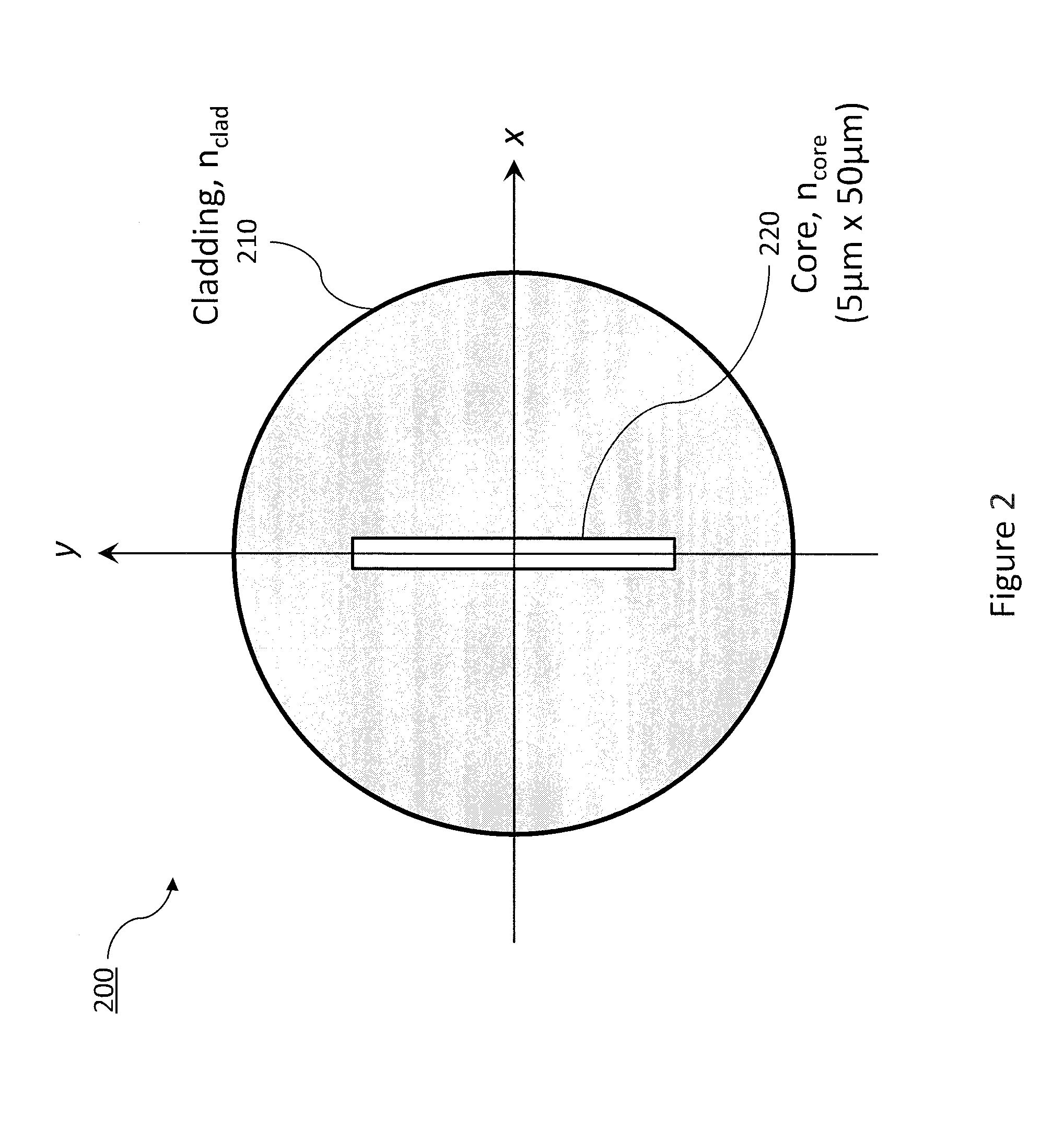
[0040]In this invention, we teach embodiments that can circumvent the prior-art system design tradeoffs described in the Background of the Invention. Embodiments are presented that enable one to utilize ribbon-core fiber amplifiers, enabling high-power scaling relative to that limited by circular-core fibers, which when combined with novel spatial optical mode transformers, can efficiently convert high-order ribbon-fiber modes to TEM00 fundamental modes, and vice versa.

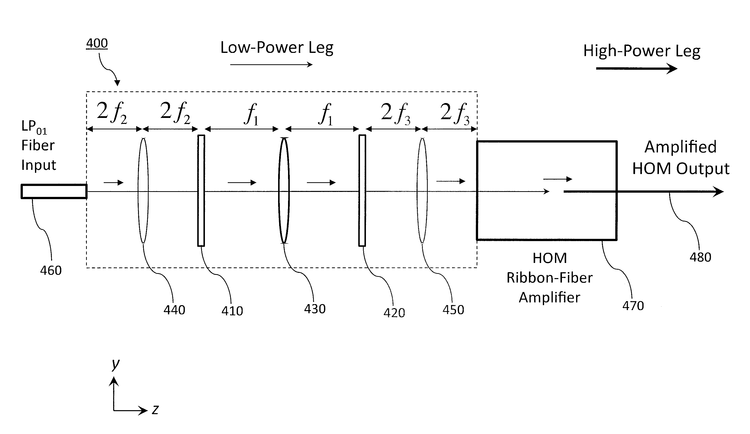
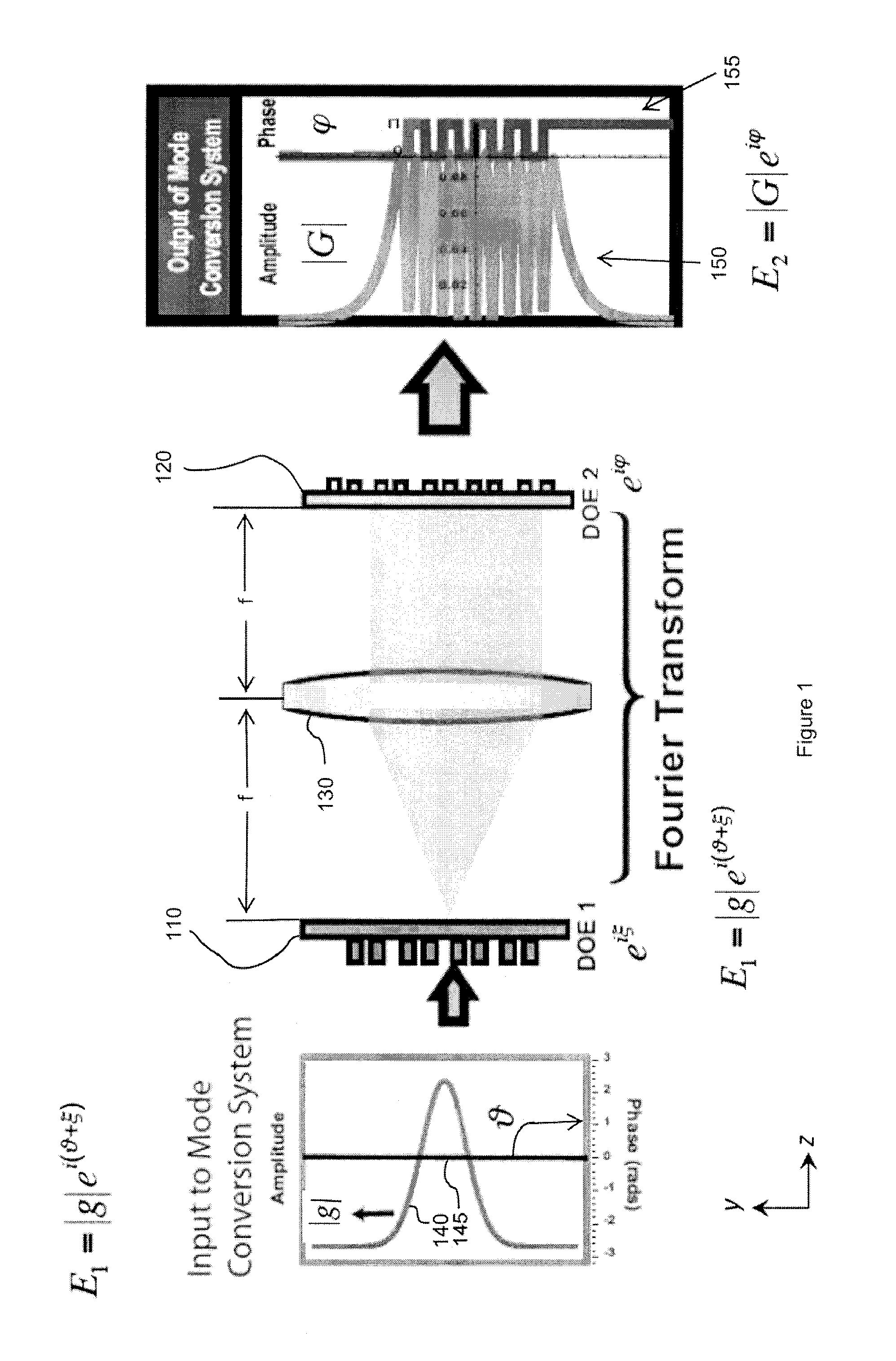
[0041]The basic modal conversion module involves a pair of diffractive-optic-elements (DOEs), situated at conjugate Fourier planes of an optical system. This configuration enables the transformation of a given input spatial profile to a specific output beam profile. As an example, a transformation module can be implemented to convert the diffraction-limited LP01 mode from a low-power fiber laser to a specific higher-order-mode (HOM) of a ribbon core fiber amplifier, and, subsequently, from the amplified HOM ribbon-fib...


PUM


Abstract

Spatial mode conversion modules are described, with the capability of efficiently transforming a given optical beam profile, at one plane in space into another well-defined optical beam profile at a different plane in space, whose detailed spatial features and symmetry properties can, in general, differ significantly. The modules are comprised of passive, high-efficiency, low-loss diffractive optical elements, combined with Fourier transform optics. Design rules are described that employ phase retrieval techniques and associated algorithms to determine the necessary profiles of the diffractive optical components. System augmentations are described that utilize real-time adaptive optical techniques for enhanced performance as well as power scaling.

Description

CROSS-REFERENCE TO RELATED APPLICATIONS[0001]This application claims the benefit of U.S. Provisional Patent Application No. 61 / 641,464 titled “Diffractive Optical Elements for Transformation of Modes in Lasers,” filed May 2, 2012, incorporated herein by reference.STATEMENT REGARDING FEDERALLY SPONSORED RESEARCH OR DEVELOPMENT[0002]The United States Government has rights in this invention pursuant to Contract No. DE-AC52-07NA27344 between the U.S. Department of Energy and Lawrence Livermore National Security, LLC, for the operation of Lawrence Livermore National Laboratory.BACKGROUND OF THE INVENTION[0003]1. Field of the Invention[0004]The present invention relates to fiber amplifiers, and more specifically, it relates to techniques for increasing the high average power produced by fiber amplifiers.[0005]2. Description of Related Art[0006]Scalable, high average power lasers are needed for materials processing and defense systems. Scientific applications such as laser-based guide star...

Claims


Application Information

Patent Timeline
IPC IPC(8): H01S3/10
CPCH01S3/10007H01S3/06729H01S3/10015H01S3/10023H01S3/1307H01S3/2333H01S3/2383H01S3/005H01S3/10053H01S3/0085G02B5/1814
Inventor SRIDHARAN, ARUN K.PAX, PAUL H.HEEBNER, JOHN E.DRACHENBERG, DERREK R.ARMSTRONG, JAMES P.DAWSON, JAY W.
Owner LAWRENCE LIVERMORE NAT SECURITY LLC
Learn More