Micromechanical device

a micromechanical and device technology, applied in the direction of electrostatic generator/motor, electrical apparatus, instruments, etc., can solve the problems of microstructure bending, significant increase of electric drive voltage, and high force effect of electrodes, and achieve the effect of effective drive mechanism and large deflection

Active Publication Date: 2013-11-14
FRAUNHOFER GESELLSCHAFT ZUR FOERDERUNG DER ANGEWANDTEN FORSCHUNG EV
View PDF1 Cites 33 Cited by
  • Summary
  • Abstract
  • Description
  • Claims
  • Application Information

AI Technical Summary

Benefits of technology

[0036]The basic principle underlying the present invention is the finding that it is possible to combine the different advantages of the different known drive principles so as to reach a more effective drive mechanism. In particular, the finding is that it is basically very profitable to use the bimorph or monomorph principle for deflecting beams or plates or other deflectable structures or deformable elements since a small lateral material strain can result in a large deflection due to the context already presented above, according to which the deflection w is proportional to the square of the length of the structure to be deflected or the deformable element, i.e. w˜l2. The inventors have recognized that it is possible to generate the necessitated material strain or contraction without the thermomechanical, electroactive or magnetoactive effects involving the problems discussed in the introductory part of the description. In particular, it is a finding of the present invention that it is possible to effect deformation of a deformable element according to the bimorph or monomorph principle by electrostatic forces. Since the forces on the electrodes of an electrostatic field in the plate capacitor assembly scale very well in the micrometer and even considerably more so in the nanometer range, due to the correl

Problems solved by technology

Thus, small electrode gaps result in a high force effect on the electrodes.
Large gaps, however, significantly increase the necessitated electric drive voltages (due to: F˜1/d2).
As a result, the microstructure is bent.
A problem associated with thermomechanical excitation is that basically sufficiently high material strains for bending micromechanical cantilevers and plates can be generated by the thermomechanical effect and a suitable material selection (for 201 and 202) [1], but the generation of the temperatures necessitated for this is problematic for three different reasons:The height of the temperatures that can be generated with a given power coupling depends on the thermal insulation (more accurately, heat flow balance) of the microstructures to be deflected with regard to their environment.
Depending on the size of the beam or plate area to be heated, high thermal insulation of the structures to be deflected might not be realized.
Thus, a relatively high power consumption of the microsystem is needed for generating the temperatures necessitated for deflection.If a resistive micro heating (=usage of ohmic “power loss”) is used, the operating range of the temperatures to be used for the target movement of the cantilever or the plate will have to be above the maximum environmental temperature of the target application.
Thus, the microsystem has high power consumption even at low target deflections [5].
Basically, the temperatures could be both increased and reduced by using the Peltier effect, but due to the low efficiency a microsystem having low power consumption is not possible here either.The amount of heat capacity (e.g. of the surrounding air) associated with the thermal insulation of the microstructures to be deflected limits the maximum possible velocity of the movement of the deflection.
This has the following consequences:If

Method used


Image

  • Micromechanical device
  • Micromechanical device
  • Micromechanical device

Examples


Embodiment Construction

[0096]Before embodiments of the present invention will be discussed in more detail below, at first, the basic principle or the basic effect underlying the subsequently described embodiments will be discussed or justified in more detail. At first, geometries for positive lateral contraction will be presented.

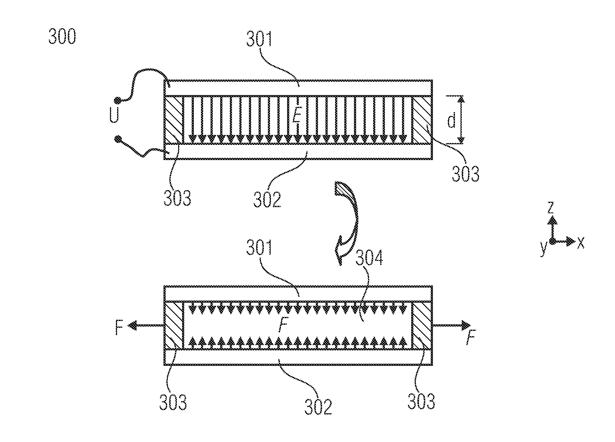
[0097]FIG. 1 shows the cross-section of a simple plate capacitor assembly 300. Here, electrodes 301 and 302 are arranged spaced apart from each other at a distance d using an electrically insulating material 303. The gap 304 between the electrodes can be filled with air, another gas or can be evacuated (vacuum) and has the permittivity ∈. If an electric voltage U is applied over the electrodes 301 and 302, an electrostatic field E will be formed. The electrostatic field exerts a vertical force Fz on both electrode areas.

[0098]If the electrodes 301 and 302 are effected in a very stiff manner (e.g. by materials having a high elasticity module or by a sufficient thickness), i.e. the...


PUM


Abstract

The force on the electrodes of an electrostatic field is used so that lateral tensile or compressive forces result which can deform a deformable element or can strongly deflect a deflectable structure. For this, a micromechanical device includes, apart from an electrode and a deformable element, an insulating spacer layer via which the electrode is fixed to the deformable element, wherein the insulating spacer layer is structured into several spaced-apart segments along a lateral direction, so that by applying an electric voltage between the electrode and the deformable element lateral tensile or compressive forces bending the deformable element along the lateral direction result. Thereby, the problem that normally accompanies electrostatic drives, namely the problem of the pull-in effect, is overcome. The deflection of the deformable element can be much larger than the gaps of the two electrodes, i.e. the above-mentioned electrode and the deformable element. A usage as a sensor is also possible.

Description

CROSS-REFERENCE TO RELATED APPLICATIONS[0001]This application is a continuation of copending International Application No. PCT / EP2011 / 050483, which was filed on Jan. 14, 2011, and which is incorporated herein by reference in its entirety.BACKGROUND OF THE INVENTION[0002]The present invention relates to a micromechanical device, such as a micromechanical actuator or a micromechanical sensor.[0003]Micromechanically produced and actively deflectable beam and plate structures are used for a large number and variety of applications. The deflectable plates are frequently also referred to as membranes due to their low thickness. For the actively deflectable beams, the term cantilever is frequently used. Table 1 lists some examples of microsystems and the functional principle of the actively deflectable microstructures is explained.TABLE 1Examples of microsystems and a description of possible functional principles of thedeflectable microstructuresFunctional principle of the activelyExample / ...

Claims


Application Information

Patent Timeline
IPC IPC(8): G02B26/08H02N1/08H02N1/00
CPCG02B26/0825H02N1/006H02N1/08G02B26/0841H01G5/16H04N1/08
Inventor CONRAD, HOLGERSCHENK, HARALDSCHIRRMANN, CHRISTIANSANDNER, THILOZIMMER, FABIANSCHMIDT, JAN-UWE
Owner FRAUNHOFER GESELLSCHAFT ZUR FOERDERUNG DER ANGEWANDTEN FORSCHUNG EV
Why Eureka
Try Eureka