Membrane reactor and process for the production of a gaseous product with such reactor

a technology of membrane reactor and gaseous product, which is applied in the direction of chemical/physical/physical-chemical stationary reactors, chemical apparatus and processes, chemical/physical/physical-chemical processes, etc., can solve the problems of economic attractiveness, mismatch between catalyst volume, heat transfer area and membrane area, and inability to select heat exchanging area and membrane area independently, so as to improve heat transfer to the catalyst, improve heat transfer, and improve the effect of heat transfer

Inactive Publication Date: 2013-12-05
NEDERLANDSE ORG VOOR TOEGEPAST-NATUURWETENSCHAPPELIJK ONDERZOEK (TNO)
View PDF1 Cites 12 Cited by
  • Summary
  • Abstract
  • Description
  • Claims
  • Application Information

AI Technical Summary

Benefits of technology

[0043]Especially, at least part of the heating channel is in physical contact with the catalyst sections. Especially, physical contact may improve heat transfer to the catalyst. Part of the heating channel, or the entire heating channel, may also be indicated as burner or burner section. In this heating channel, for instance methane may be burned to generate heat. To this end, for instance natural gas and air are fed to the heating channel and ignited.
[0044]In a further embodiment, at least part of the heating

Problems solved by technology

Consequently the catalyst volume, the heat exchanging area and membrane area cannot be selected independently in the design.
Given the inherently low flux of the reaction or side product to be removed, for example hydrogen, through a given membrane area, compared to the rate in which it can be produced in a certain catalyst volume, and the heat flux required to enable the reaction to produce the reaction product, in prior art membrane reactor designs there is a mismatch between the catalyst volume, heat transfer area and membrane area.
However, from a practical point of view this is suitable only for a process in which a limited number of steps is necessary.
Calculations (see examples) for steam reforming have shown that a limited number of sequential steps, for example 5 or less, the conversion of feed wh

Method used


Image

  • Membrane reactor and process for the production of a gaseous product with such reactor
  • Membrane reactor and process for the production of a gaseous product with such reactor
  • Membrane reactor and process for the production of a gaseous product with such reactor

Examples


example 1

Comparison of Packing Density of Membrane Tubes in the Novel and in a Standard Membrane Reactor

[0093]Calculated: for a membrane section the membrane cross-sectional area / total cross-sectional area [%] and number of membranes per m2. Starting points for novel concept:[0094]Membrane diameter=dm (example membranes typical dm=1.4 cm)[0095]Because of flanges a certain distance between membranes is necessary, and we assume the flange leads to a minimum distance between the membranes f=½ dm (or 1.4 / 2 cm)

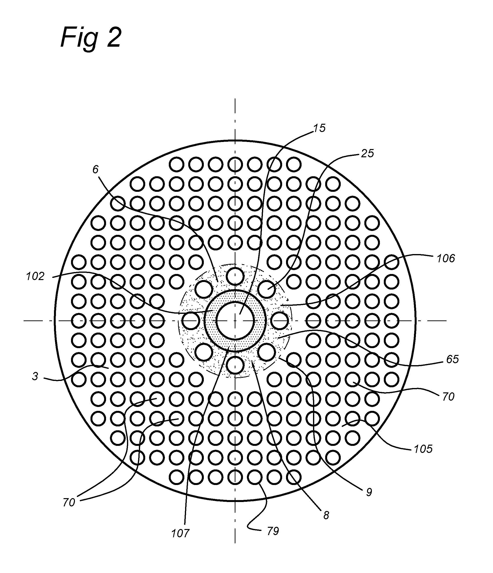
[0096]For a triangular arrangement, as shown in FIG. 4a, the ratio between the membrane area and the total area is equal to 23% corresponding to 1500 membranes / m2.

[0097]In the typical tube-in-tube configuration shown in FIG. 4b (reference example), there are membrane / catalyst tubes and burner or heater tubes. The reference dc indicates the thickness of the catalyst layer. In this case a typical arrangement is assumed where every burner is surrounded by 6 membranes and correspondingly each m...

example 2

Calculation of the Velocity in a Membrane Reactor for the Tube-In-Tube Concept (Based on a Steam Methane Reformer Membrane Reactor: CH4+H2O→4H2|CO2)

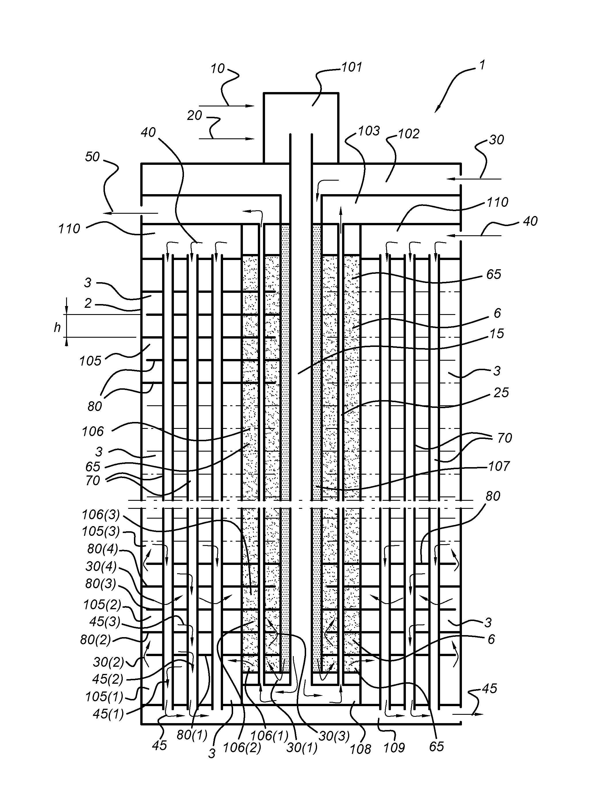
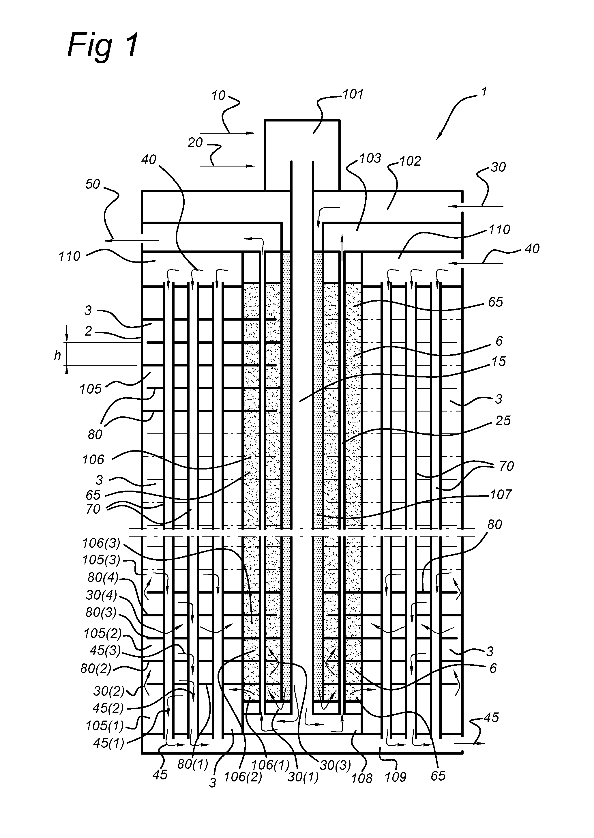
[0103]In a tube-in-tube configuration, the feed flow is determined by hydrogen flux through the membrane. Theoretically, at 100% conversion for every 4 moles of H2 removed by the membrane, 1 mole of methane needs to be supplied. Typically per mole of methane 2-3 moles of steam are supplied.

[0104]As a typical example we assume:[0105]Membrane diameter=1.4 cm[0106]Cat bed thickness: 5 mm[0107]Catalyst particle size: 1 mm

[0108]Based on an assumed length of catalyst / membrane tube of 6.5 m, the velocity of the gas will be at the feed side inlet will be: 0.2 m / s. For the hydrogen production of 1322 mol / s this will give flux of 553 mol / s. For example, for shorter tubes the velocities will be lower, i.e. if the length of the tube is 3.5 meter the velocity is only 0.02 m / s. As more hydrogen is removed from the mixture along the tube, the velocity ...

example 3

How Many Steps are Required in a Sequential System (Reaction-Separation-Reaction-Separation, etc) to Achieve a High Conversion

[0110]Again we have considered hydrogen production through the steam methane reaction using a membrane reactor. The following starting points have been used:[0111]Hydrogen recovery pressure (permeate pressure=5.5 bar). This is close to the economic optimum (cost required for compression⇄membrane area) determined for a typical industrial hydrogen production system;[0112]The membrane area Amen=5100 m2 for a 100 000 Nm3 / h plant. This has again been determined an economic optimum (compromise between investment cost and conversion).[0113]Operating temperature=650° C. (maximum operating temperature for some of the membranes).

[0114]The base case is the fully integrated tube-in-tube system. For these conditions we find a methane conversion equal to 96% and a hydrogen recovery=95%

H2recov%=H2,permH2,perm+H2,ret·100%

[0115]For the non-integrated design (R-S-R-S-R-S- . ....


PUM


Abstract

The invention provides an integrated catalyst and membrane reactor for the production a predetermined gas such as hydrogen. The reactor comprises a gas flow channel, comprising a plurality of alternating catalyst sections and membrane sections, wherein each catalyst section comprises a catalyst bed and each membrane section comprises a plurality of membranes, and wherein the membranes are selectively permeable for the predetermined gaseous species.

Description

FIELD OF THE INVENTION[0001]The invention relates to a membrane reactor and to a process for the production of H2 with such reactor.BACKGROUND OF THE INVENTION[0002]Membrane reactors are known in the art. For example, WO2010 / 086635 discloses a reactor wherein a synthesis gas is subjected to a water-gas shift reaction, and carbon dioxide is separated from the shifted gas mixture by a CO2-selective membrane, thereby generating a hydrogen-enriched gas mixture.[0003]WO2004 / 022480 describes a process and apparatus for the production of high purity hydrogen by steam reforming. The apparatus is an integrated reactor for steam reforming of a hydrocarbon to produce H2 and CO2, with minimal CO in the H2 stream. The reactor contains multiple flameless distributed combustion (FDC) chambers and multiple hydrogen-selective, hydrogen-permeable, membrane tubes. The feed and reaction gases flow through the reactor radially or axially. This document also describes different configurations of baffles ...

Claims


Application Information

Patent Timeline
IPC IPC(8): B01J7/00C01B3/38
CPCB01J7/00C01B3/38B01J19/006B01J19/2475B01J19/2485B01J8/009B01J8/0465C01B3/16B01J2208/00504B01J2208/0053B01J2208/025C01B2203/0233C01B2203/0238C01B2203/0261C01B2203/0283C01B2203/041C01B2203/1047C01B2203/1058B01J8/04B01J19/24B01J19/00
Inventor DE GROOT, ARENDVAN DELFT, YVONNE CHRISTINESARIC, MARIJA
Owner NEDERLANDSE ORG VOOR TOEGEPAST-NATUURWETENSCHAPPELIJK ONDERZOEK (TNO)
Why Eureka
Try Eureka