Process for treating fluids

a technology for fluid treatment and fluids, applied in the field of fluid treatment, can solve the problems of high cost, dangerous situation, and high cost of fluid treatment, and achieve the effects of improving the mixture of effluent and ozone, accelerating mass transfer, and improving the mixing rate of effluen

Active Publication Date: 2013-12-12
BRISBEN WATER SOLUTIONS
View PDF4 Cites 6 Cited by
  • Summary
  • Abstract
  • Description
  • Claims
  • Application Information

AI Technical Summary

Benefits of technology

[0013]The instant invention is directed to an improved treatment apparatus that introduces high intensity acoustic energy and ozone into a conditioning container to provide a mechanical separation of materials by addressing the non-covalent forces of particles or van der Waals force. The invention further discloses hydrodynamic cavita...

Problems solved by technology

In many such instances the treatment of such fluids can be extremely expensive.
For example, the global direct costs to oil companies for treating water used in oil and gas recovery surpassed $20 billion in 2007, with expenses skyrocketing in the following years.
Anaerobic bacteria can be include an acid producing bacteria such as APB that grows on metal and secretes acid producing corrosion, or SRB which is a sulfate reducing bacteria that produces hydrogen sulfide and has the potential to create a dangerous situation and literally shut down a well.
The US Department of Energy (DOE) has called produced water “by far the largest single volume byproduct or waste stream associated with oil and gas production.” The DOE further terms its treatment a serious environmental concern and a significantly growing expense to oil and gas producers.
While the instant cavitation reactor has a benefi...

Method used


Image

  • Process for treating fluids
  • Process for treating fluids
  • Process for treating fluids

Examples


Embodiment Construction

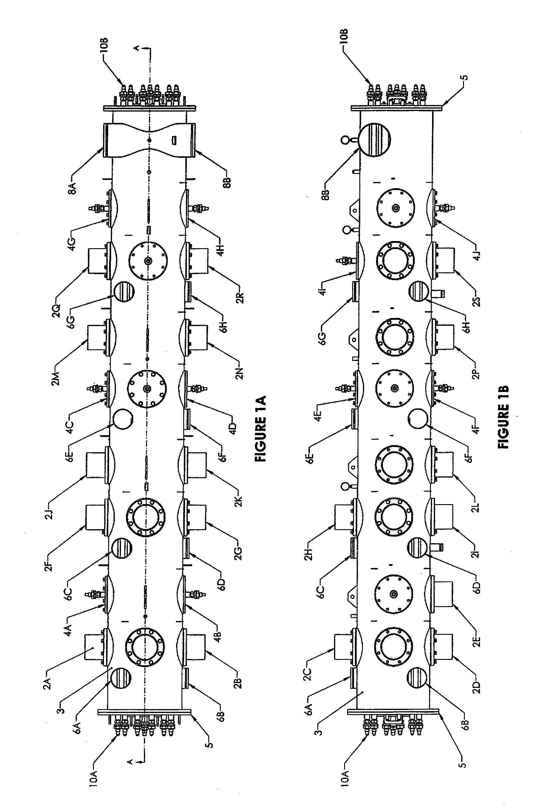
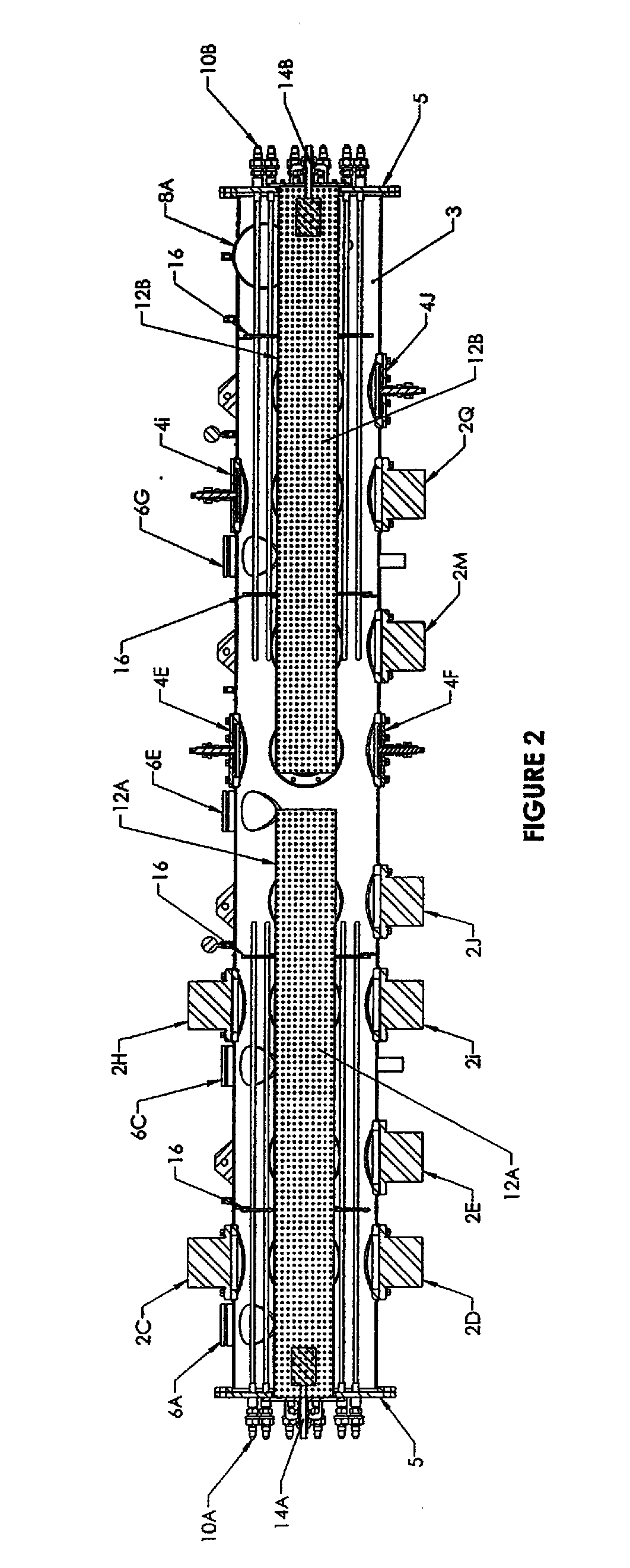
[0051]FIG. 1A is a top view of the main reactor 1 of the treatment system and FIG. 1B is a side view of the main reactor 1. The main reactor 1 includes a cylindrical housing 3 that is, by way of example, approximately 16.5 feet long and 2 feet in diameter. A circular end plate 5 is mounted on each end of the cylindrical housing 3. Located along the length of the cylindrical housing are eighteen ultrasonic transducers 2A,2B,2C,2D,2E,2F, 2G, 2H, 2J,2K, 2L, 2M,2N, 2P,2Q, 2R and 2S. Each of the ultrasonic transducers is rated at 500 W capacity and is also equipped with a heated plate that is rated at 1000 W. At given flow rates it maintains a ΔT of 40 degrees that enhances the precipitation within the main reactor. Each transducer can produce an acoustic output in the range of 16 to 20 KHz and can be individually adjusted to the desired output frequency. Each transducer includes a diaphragm that is balanced with the help of a pressure compensation system so that a maximum amount of ultr...


PUM

PropertyMeasurementUnit
Pressureaaaaaaaaaa
Hydrodynamic waveaaaaaaaaaa

Abstract

Disclosed is an improved water treatment process that operates on a continuous flow of fluids that are subjected to hydrodynamic waves, acoustic ultrasonic waves in combination with injected ozone and electro chemical treatment. The treatment system provides a cost efficient and environmentally friendly process and apparatus for cleaning and recycling fluids as contaminated as frac water, used to stimulate gas production from shale formations, as well as other types of fluids having various levels of contaminants such as aerobic and anaerobic bacteria and suspended solids. The calcium carbonate scaling tendency is reduced to an acceptable level without the use of acids, ion exchange materials, or anti scaling chemicals which is of economical and environmental significance and benefit.

Description

CROSS-REFERENCE TO RELATED APPLICATIONS[0001]This application is related to U.S. patent application Ser. No. 13 / 450,172, entitled “Apparatus for Treating Fluids”, filed on Apr. 18, 2012. In addition, this application is a continuation-in-part U.S. patent application Ser. No. 13 / 019,113, entitled “Transportable Reactor Tank”, filed Feb. 1, 2011, which is a continuation-in-part of U.S. patent application Ser. No. 12 / 765,971, entitled “Improved Reactor Tank”, filed Apr. 23, 2010, which is a continuation-in-part of U.S. patent application Ser. No. 12 / 399,481, entitled “Enhanced Water Treatment for Reclamation of Waste Fluids and Increased Efficiency Treatment of Portable Waters”, filed Mar. 6, 2009, now U.S. Pat. No. 7,699,988, issued Apr. 20, 2010, which is a continuation-in-part of U.S. patent application Ser. No. 12 / 184,716, entitled “Enhanced Water Treatment for Reclamation of Waste Fluids and Increased Efficiency Treatment of Portable Waters”, filed Aug. 1, 2008, now U.S. Pat. No. ...

Claims


Application Information

Patent Timeline
IPC IPC(8): C02F9/12C02F1/52C02F1/48C02F5/02C02F1/36C02F1/78
CPCC02F1/78C02F1/463C02F2001/46152C02F2001/46171C02F2103/365C02F2201/008C02F2303/04C02F2303/22C02F1/36B01F23/2323B01F23/237613B01F25/3121B01F25/31242B01F25/43161B01F33/5021B01F33/813C02F1/48C02F1/52C02F5/02
Inventor MCGUIRE, DENNISJAKHETE, SANJEEV
Owner BRISBEN WATER SOLUTIONS
Why Eureka
Try Eureka