
Internal combustion engine featuring partial shutdown and method for operating an internal combustion engine of this kind

a technology of internal combustion engine and partial shutdown, which is applied in the direction of machines/engines, electrical control, ignition control, etc., can solve the problems of high cost of variable valve gears, and inability to use production vehicles, so as to reduce the effectiveness or quality of combustion, reduce the disadvantage of fuel consumption and pollutant emissions, and expand the load range

Active Publication Date: 2013-12-19
FORD GLOBAL TECH LLC
View PDF26 Cites 22 Cited by
  • Summary
  • Abstract
  • Description
  • Claims
  • Application Information

AI Technical Summary

Benefits of technology

This patent describes an internal combustion engine that can improve its efficiency. The engine has a system for controlling the amount of charge air that is supplied to the engine's cylinders. This is done by using a throttling element in the intake line of each cylinder. This throttling element can be opened or closed to adjust the amount of charge air that is sent to the cylinders. By controlling this charge air, the engine can improve its performance and fuel efficiency during certain operating conditions. This is without the need for expensive switchable valve gears.

Problems solved by technology

Fuel consumption, and hence efficiency, is problematic, especially in the case of spark-ignition engines, e.g. in the case of internal combustion engines with applied ignition.
This also explains why quantity control proves disadvantageous precisely in part-load operation, since low loads use a high degree of throttling and pressure reduction in the intake system, thereby causing a rise in exhaust and refill losses with decreasing load and increasing throttling.
However, variable valve gears are very expensive and are therefore often unsuitable for use in production vehicles.
The exhaust and refill losses generated in this case reduce the improvements as regards fuel consumption and efficiency which are achieved by partial shutdown and counteract said improvements, with the result that the benefit of partial shutdown is at least partially lost, that is to say that, overall, partial shutdown actually involves a less significant improvement.
In practice, it is not expedient to remedy the disadvantageous effects described above by providing switchable valve gears since switchable valve gears, like variable valve gears, are very expensive.
Moreover, switchable valve gears would lead to further problems in the case of internal combustion engines pressure-charged by exhaust turbocharging since the turbine of an exhaust turbocharger has to be designed for a particular exhaust gas quantity and hence also for a particular number of cylinders.
The effects described above lead to a restriction in the application of partial shutdown, namely to a restriction of the load range in which partial shutdown can be employed.
The reduced charge air quantity which is fed to the cylinders that are in operation during partial shutdown reduces the effectiveness or quality of combustion and has a disadvantageous effect on fuel consumption and pollutant emissions.
However, this procedure has the disadvantage that the pressure-charging behavior is inadequate when all the cylinders are operated.
In that case, however, the exhaust back pressure in the exhaust system upstream of the turbine would simultaneously increase, leading in turn to higher exhaust and refill losses in the cylinders that continue in operation.
In the case of the internal combustion engine according to the disclosure, the charge air supply to the cylinders that have been switched off, e.g. the charge air quantity supplied during partial shutdown, can be reduced and controlled, or even cut off if appropriate, without fitting the switchable cylinders with switchable valve gears, which give rise to high costs.

Method used


Image

  • Internal combustion engine featuring partial shutdown and method for operating an internal combustion engine of this kind
  • Internal combustion engine featuring partial shutdown and method for operating an internal combustion engine of this kind
  • Internal combustion engine featuring partial shutdown and method for operating an internal combustion engine of this kind

Examples


Embodiment Construction

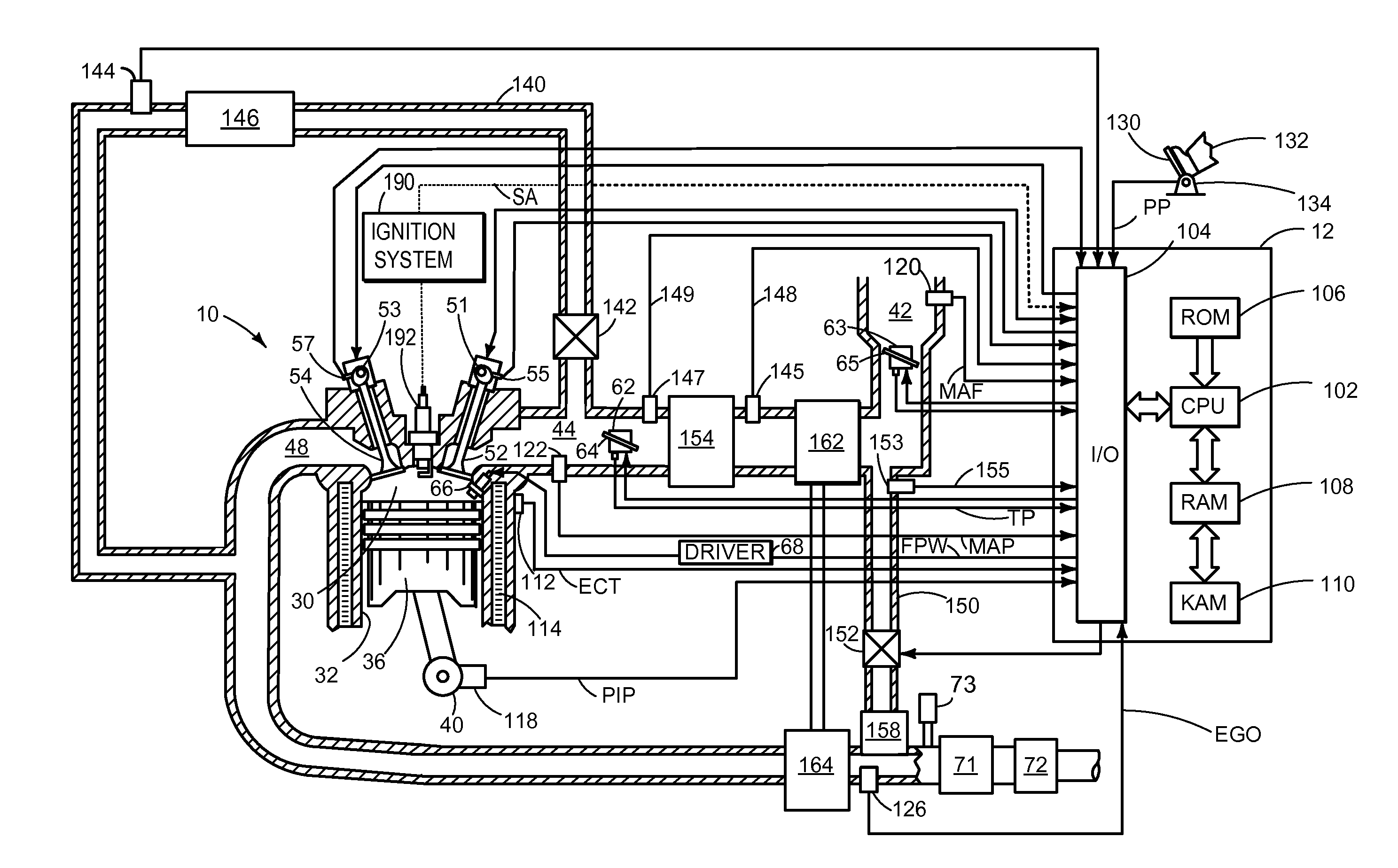
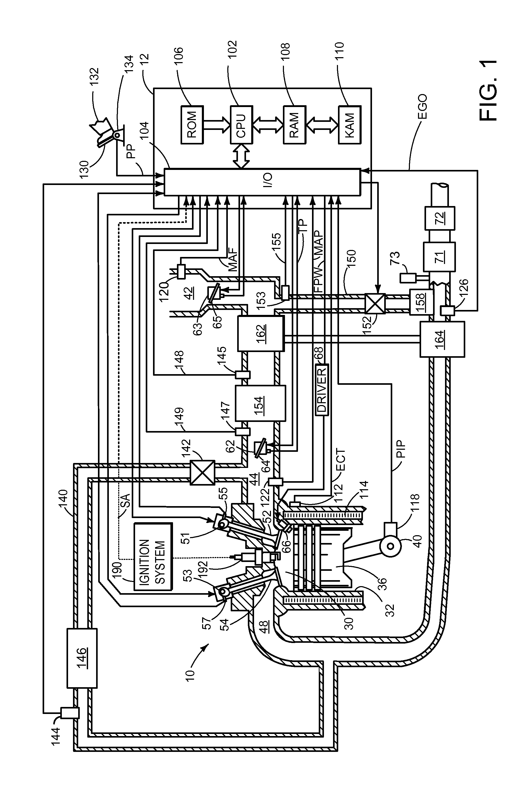
[0022]Referring now to FIG. 1, a schematic diagram of one cylinder of multi-cylinder engine 10, which may be included in a propulsion system of an automobile, is shown. Engine 10 may be controlled at least partially by a control system including controller 12 and by input from a vehicle operator 132 via an input device 130. In this example, input device 130 includes an accelerator pedal and a pedal position sensor 134 for generating a proportional pedal position signal PP. Combustion chamber (e.g., cylinder) 30 of engine 10 may include combustion chamber walls 32 with piston 36 positioned therein. In some embodiments, the face of piston 36 inside cylinder 30 may have a bowl. Piston 36 may be coupled to crankshaft 40 so that reciprocating motion of the piston is translated into rotational motion of the crankshaft. Crankshaft 40 may be coupled to at least one drive wheel of a vehicle via an intermediate transmission system. Further, a starter motor may be coupled to crankshaft 40 via ...


PUM


Abstract

Systems and methods are provided for an engine wherein one group of cylinders is active and a second group of cylinders is switchable, such that under low loads the second group of cylinders is deactivated, and under high loads the second group of cylinders is activated. Following deactivation of the second group of cylinders a throttling element in an intake line for the second group of cylinders is gradually closed. The closing of the throttling element may reduce pumping losses and thus increase engine efficiency.

Description

CROSS REFERENCE TO RELATED APPLICATIONS[0001]The present application claims priority to German Patent Application No. 102012209912.3, filed on Jun. 13, 2012, the entire contents of which are hereby incorporated by reference for all purposes.TECHNICAL FIELD[0002]The present application relates to cylinder deactivation in internal combustion engines.BACKGROUND AND SUMMARY[0003]It is a fundamental aim in developing internal combustion engines to minimize fuel consumption, with increased overall efficiency being at the forefront of the efforts made. Fuel consumption, and hence efficiency, is problematic, especially in the case of spark-ignition engines, e.g. in the case of internal combustion engines with applied ignition. The reason lies in the fundamental operating method of the spark-ignition engine. Load control is generally performed by a throttle valve provided in the intake system. By adjusting the throttle valve, the pressure of the induced air behind the throttle valve can be r...

Claims


Application Information

Patent Timeline
Patent Type & Authority Applications(United States)
IPC IPC(8): F02D17/02
CPCF02D17/02F02D13/06F02D17/023F02D41/123
Inventor CHEN, GUOHUIWILLEMS, WERNERBARTSCH, LEONHARDRUHLAND, HELMUT HANS
Owner FORD GLOBAL TECH LLC
Learn More