
Radiation thermometer using off-focus telecentric optics

a telecentric optics and thermometer technology, applied in the direction of optical radiation measurement, instruments, coatings, etc., can solve the problems of reducing the effective range over which a telecentric lens system can provide an isometric image at a given setting, requiring neither high-quality imaging optics nor sophisticated mountings for fine tuning an image, and limiting the contribution of stray radiation. , to achieve the effect of adding light rejection

Active Publication Date: 2013-12-26
VEECO INSTR
View PDF7 Cites 15 Cited by
  • Summary
  • Abstract
  • Description
  • Claims
  • Application Information

AI Technical Summary

Benefits of technology

The patent text describes a way to use telecentric lens systems in machine vision systems to capture clear, crisp images of high magnification. However, these systems have limited effective range and are expensive. The invention proposes a new approach that takes advantage of the telecentric concept to capture a collimated beam of radiation emitted from a target surface, without the need for high quality imaging optics and sophisticated mountings. The optical arrangement is designed to collect the radiation from each point on the target with the same angle, reducing parallax within the image. This approach provides a cost-effective solution for off-focus or non-contact metrology applications.

Problems solved by technology

First, in a telecentric optical arrangement, the chief rays that are captured from the target are substantially parallel to the optical axis, which substantially limits the stray radiation contribution, particularly if the target has a strong specular reflectivity component.
However, the effective range over which a telecentric lens system can provide an isometric image at a given setting is quite limited.
Such an arrangement requires neither high quality imaging optics nor sophisticated mountings for fine tuning an image.

Method used


Image

  • Radiation thermometer using off-focus telecentric optics
  • Radiation thermometer using off-focus telecentric optics
  • Radiation thermometer using off-focus telecentric optics

Examples


Embodiment Construction

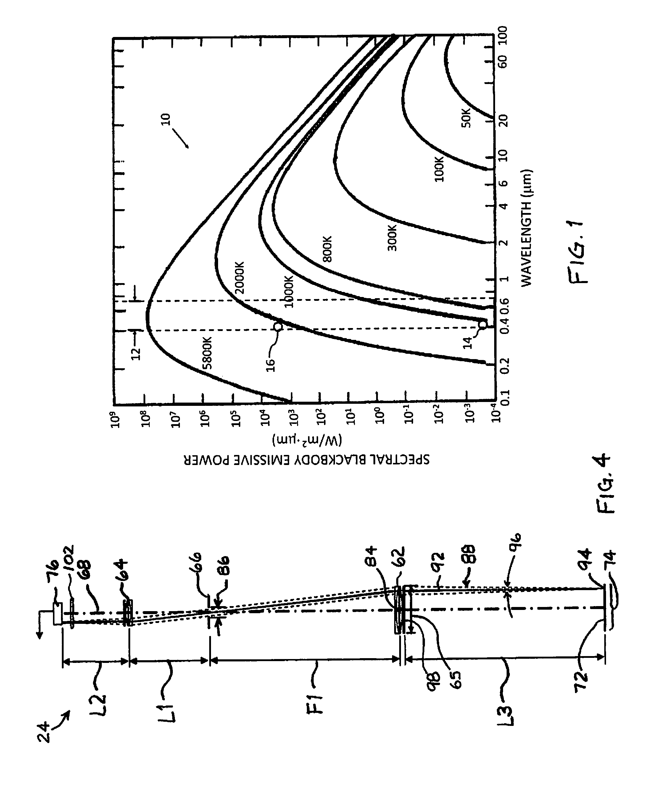
[0024]Referring to FIG. 1, a family of curves 10 depicting the spectral blackbody emissive power in accordance with Planck's law at various temperatures is presented. The visible spectral region 12, coinciding approximately with the 400 nm to 700 nm wavelength band, is also identified in FIG. 1. In relation to the previous discussion of the effect of temperature on the blackbody emissive power at 410 nm, first and second reference points 14 and 16 are identified in FIG. 1 at 1073 K and 2073 K, respectively (corresponding to 800° C. and 1800° C., respectively).

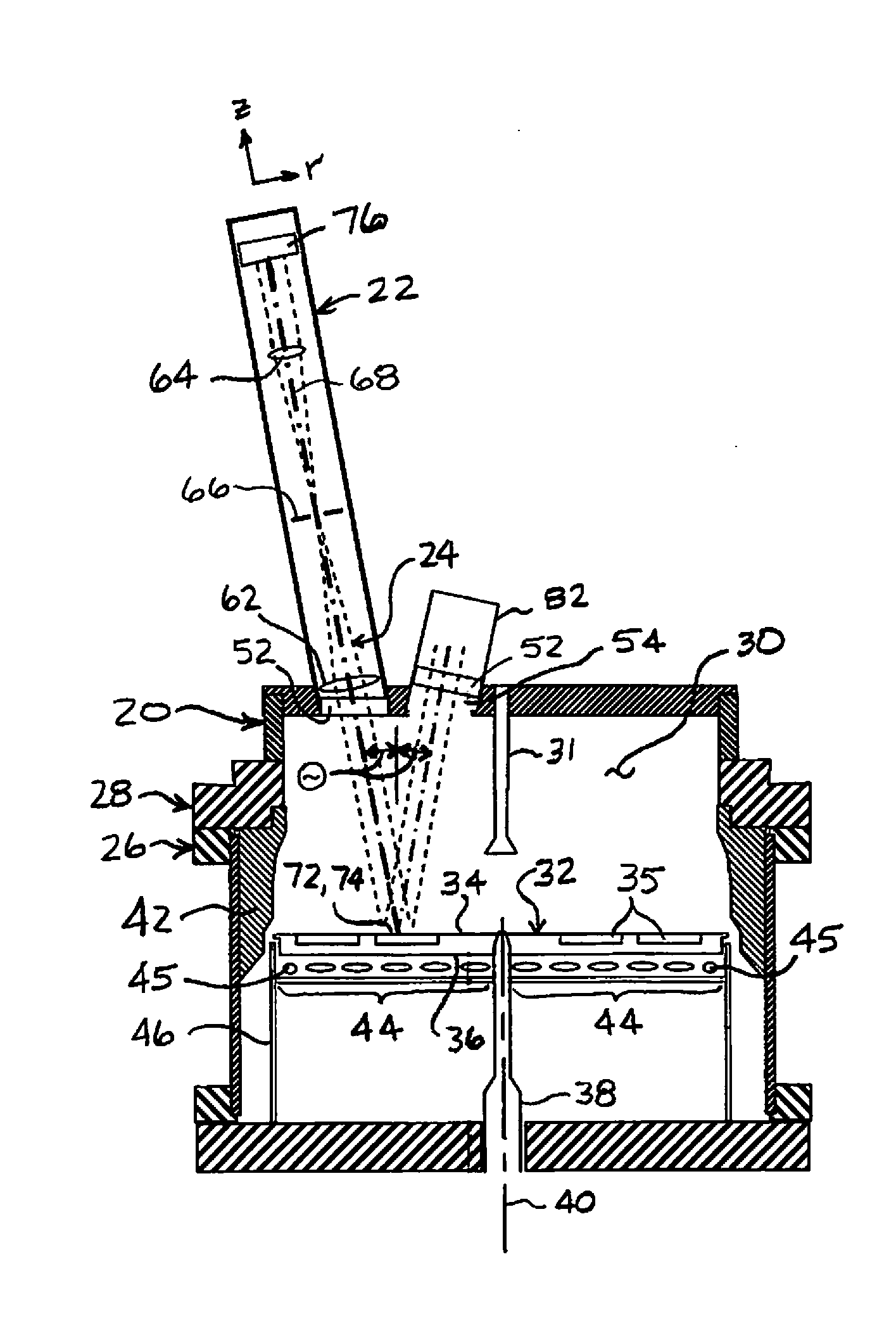
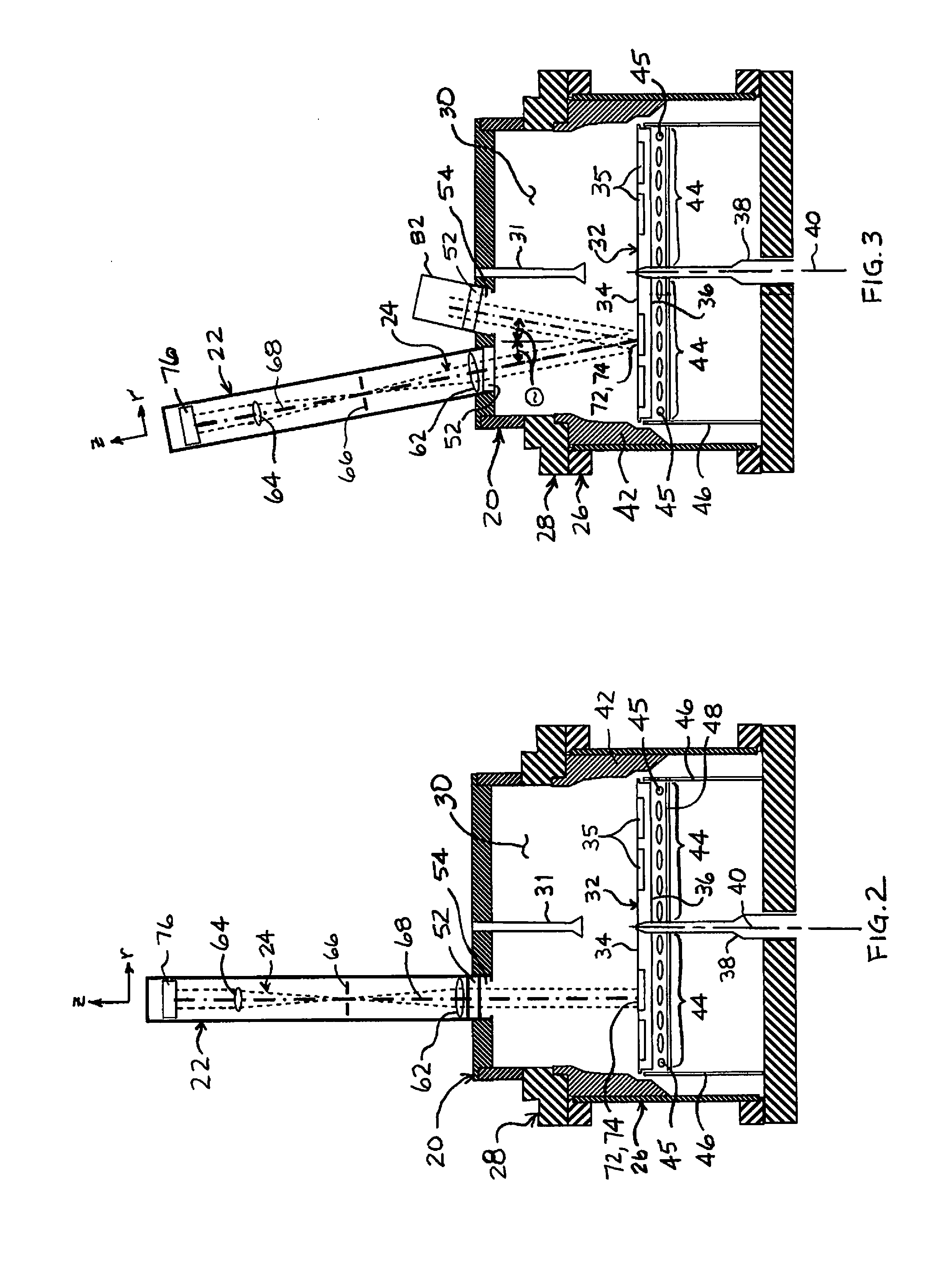
[0025]Referring to FIGS. 2 and 3, a MOCVD reactor system 20 utilizing a radiation thermometer 22 having an off-focus telecentric optical arrangement 24 is depicted in embodiments of the invention. The MOCVD reactor system 20 includes a reactor chamber 26 operatively coupled with a flow flange 28 to define an enclosure 30. The flow flange 28 includes laminar flow plates 31 through which the gases for the MOCVD process are introd...


PUM

PropertyMeasurementUnit
Widthaaaaaaaaaa
Widthaaaaaaaaaa
Widthaaaaaaaaaa

Abstract

A radiation thermometer utilizing an off-focus telecentric lens arrangement in chemical vapor deposition reactors. An object assembly of one or more optical components is positioned at a distance equal to its focal length from an aperture stop. The aperture stop is dimensioned so that the chief rays are substantially parallel with the optical axis of the object assembly, and so that the rays that pass through the aperture stop define a narrow solid angle about the chief rays. The off-focus telecentric arrangement thus configured is focused at infinity, but is utilized to capture radiation from a relatively proximate target (e.g., within a couple meters) that is out of focus. The capture of collimated radiation from the target diminishes the contribution of stray radiation, particularly with targets having a highly specular surface.

Description

FIELD OF THE INVENTION[0001]The disclosure is directed generally to radiation thermometers or pyrometers, and more specifically to collection optics used therefor.BACKGROUND[0002]Metalorganic Chemical Vapor Deposition (MOCVD) is a chemical vapor deposition technique for growing crystalline layers in processes such as the production of semiconductors. The MOCVD process is implemented in a reactor chamber with specially designed flow flanges that deliver uniform reactor gas flows to the reactor chamber.[0003]The temperature of the crystalline layers during the MOCVD process are typically measured using non-contact devices such as radiation thermometers or pyrometers. Such crystalline growth materials include silicon carbide (SiC), zinc selenide (ZnSe), and gallium nitride (GaN) based materials such as GaN and AlGaN. Certain substrates crystalline growth materials have emission characteristics that limit the wavelength of operation for radiation thermometry. For example, GaN, grown on ...

Claims


Application Information

Patent Timeline
IPC IPC(8): G01J5/02
CPCG01J5/0831C23C16/44G01J5/0007G01J5/06G01J5/0806G01J5/0859
Inventor TAS, GURAYZHOU, JINGKWON, DAEWON
Owner VEECO INSTR
Learn More