
Plate for a shield can for an SMD process, manufacturing method thereof, and shield can using the plate

Inactive Publication Date: 2014-01-30
SONG MIN HWA
View PDF5 Cites 7 Cited by
  • Summary
  • Abstract
  • Description
  • Claims
  • Application Information

AI Technical Summary

Benefits of technology

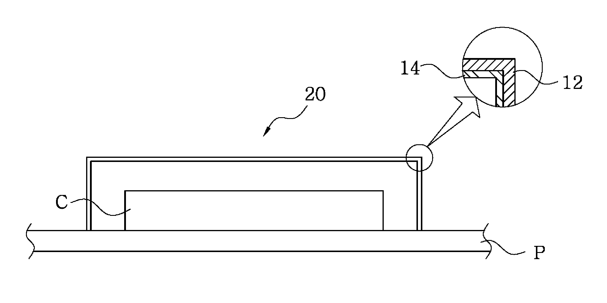
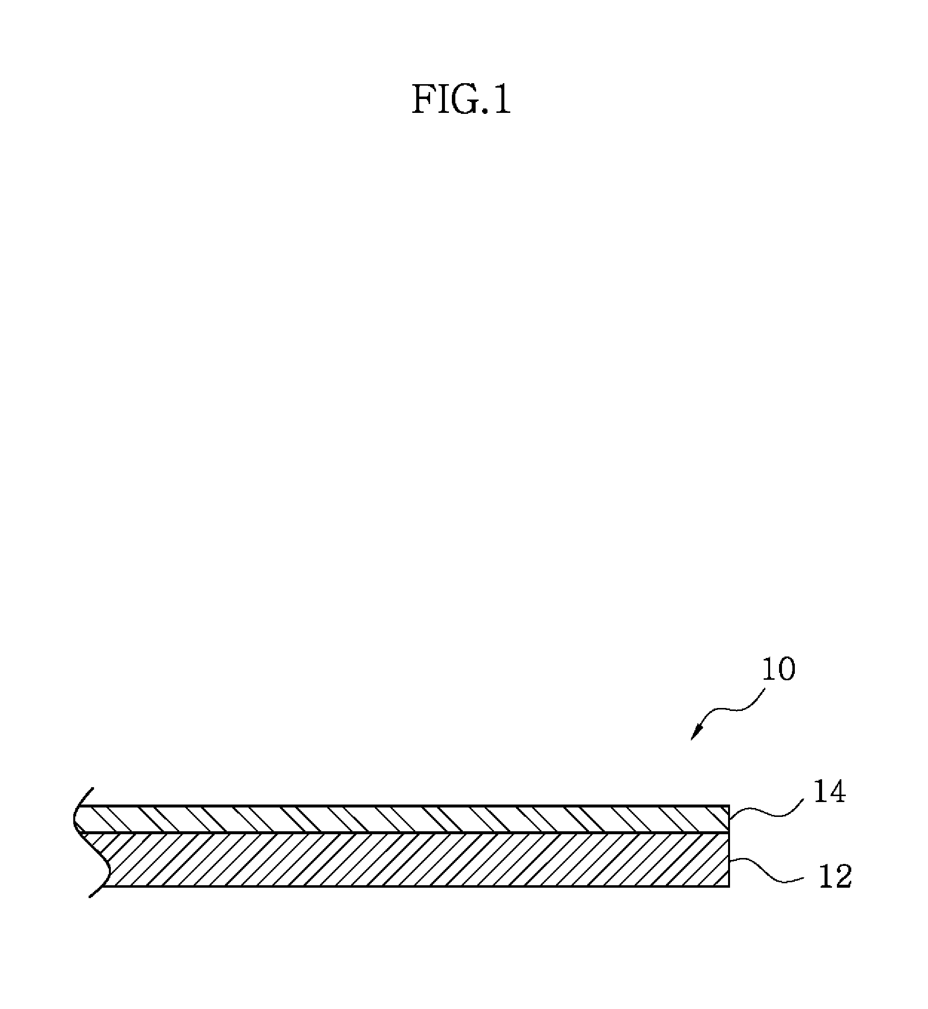
The present invention provides a shield can with excellent electromagnetic wave shielding and insulation as well as high heat-resistance. The shield can plate can effectively shield electromagnetic waves due to the conductivity of the metal layer and is highly insulated from electronic components. The insulating layer made of synthetic resin material, such as PET and PEN, is resistant to high temperatures caused by soldering. The shield can is reliable without the need for additional insulating tape and can be manufactured through a simple process with excellent material properties and economics.

Problems solved by technology

However, recently, in most cases, an electromagnetic wave means an electromagnetic noise which is emitted from electronic components or may have an effect on the electronic components.
The clip type shield can has a disadvantage of complicated process and high costs due to formation of separate clips on a PCB although it requires no material property except conductivity of a housing and insulation of an insulating tape.
Accordingly, a process for this requires additional processes, high costs and much time as it relies entirely on a manual work.
In addition, for the SMD type shield can, an insulating property may be frequently lost as an adhesive material of an insulating tape is melted due to high temperature soldering to contaminate electronic components or separate the insulating tape.

Method used


Image

  • Plate for a shield can for an SMD process, manufacturing method thereof, and shield can using the plate
  • Plate for a shield can for an SMD process, manufacturing method thereof, and shield can using the plate
  • Plate for a shield can for an SMD process, manufacturing method thereof, and shield can using the plate

Examples


example 1

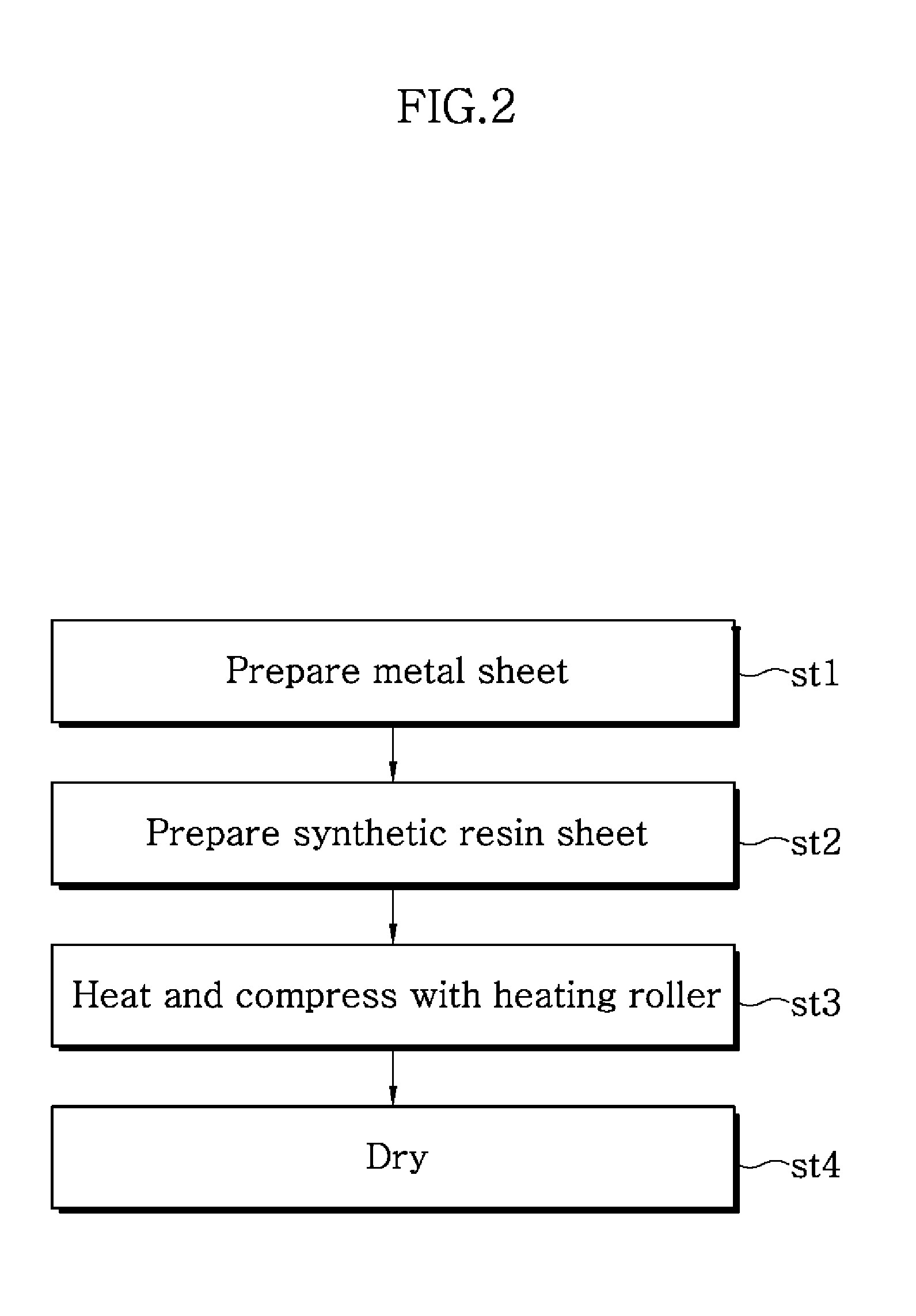
[0042]A shield can plate was manufactured by drying a laminate of a phosphor bronze-made conductive layer 12 as a 0.15 mm-thick metal sheet and a PET-made insulating layer 14 as a 50 μm-thick synthetic resin sheet after passing it through a pair of compressive rollers of 250° C. and 20 Kgf / cm2 at a speed of 2.5 m / min. Then, a first specimen was prepared by cutting the laminate to a size of 183 mm×180 mm. In addition, a second specimen was prepared by cutting PET to the same size for comparison in material property with the first specimen.

[0043]Subsequently, the first and second specimens were put in a hot wind circulation drier (JFC-301 available from JONGRO Industrial Co. Ltd.,) and their state change was observed by naked eyes at 250° C. and 260° C. with lapse of 30 seconds, 60 seconds and 90 seconds. Table 2 shows results of the observation.

TABLE 2TemperatureTimeState change(° C.)(sec)First specimenSecond specimen25030Not changedEdge curled60Not changedEdge severely curled90Not c...


PUM

PropertyMeasurementUnit
Temperatureaaaaaaaaaa
Thicknessaaaaaaaaaa

Abstract

The shield can plate for a SMD process in accordance with the present invention, includes: a metal conductive layer which is made of one selected from a group consisting of copper (Cu), zinc (Zn), nickel (Ni), silver (Ag), iron (Fe) and chromium (Cr) or an alloy thereof, or clad metal, performs an electromagnetic shielding function and maintains a physical structure when a shield can is constructed; an insulating layer which is made of one or more of polyethylene terephthalate (PET) and polyethylene naphthalate (PEN), which are crystalline polymers, wherein the insulating layer is laminated on one side of the metal conductive layer; and a silane-based coupling layer interposed between the metal conductive layer and the insulating layer.

Description

CROSS-REFERENCE TO RELATED APPLICATION[0001]This application claims the benefit of Korean Application No. 10-2011-0034180, filed on Apr. 13, 2011, with the Korean Intellectual Property Office, the disclosure of which is incorporated herein by reference.BACKGROUND OF THE INVENTION[0002]1. Field of the Invention[0003]The present invention relates to a shield can, and more particularly, to a shield can plate with high heat resistance and insulating property, which serves as a shield can basic material for shielding electronic components from an electromagnetic wave, a method of manufacturing the shield can plate, and a shield can which is manufactured with the shield can plate and covers the electronic components on a printed circuit board (PCB).[0004]2. Description of the Related Art[0005]Recent rapid advancement in electronics accounts for an increasing share of electronic components throughout the whole industrial fields including development of various electronic communication devi...

Claims


Application Information

Patent Timeline
IPC IPC(8): H05K9/00H05K13/00
CPCH05K13/00H05K9/0049H05K9/0084B32B15/08B32B15/09B32B2311/08B32B2311/12B32B2311/20B32B2311/22B32B2311/30B32B2457/08B32B7/12B32B15/20B32B27/36B32B2307/212Y10T156/10Y10T428/31663H05K9/0026H05K9/00H05K9/0024
Inventor SONG, MIN HWAOH, EUN GYO
Owner SONG MIN HWA
Learn More