
Use of a Fiber Conduit Contactor for Metal and/or Metalloid Extraction

a contactor and fiber conduit technology, applied in the direction of quarries, separation processes, treatment water, etc., can solve the problems of high cost, high cost, and inability to meet environmental regulations, and achieve the removal of chemical species from fluidic streams and solids, relatively expensive and dangerous,

Active Publication Date: 2014-03-20
CHEMTOR LP
View PDF2 Cites 21 Cited by
  • Summary
  • Abstract
  • Description
  • Claims
  • Application Information

AI Technical Summary

Benefits of technology

The patent describes a process that uses fiber conduit reactors to extract metal elements, metal compounds, metalloid elements, and metalloid compounds from a fluid stream. The process involves introducing two streams of material into the conduit reactor: one stream containing an extractant and another stream containing the metal elements, compounds, oralloid elements / compounds. The two streams are in contact, and the extractant interacts with the metal elements, compounds, oralloid elements / compounds to extract them from the second stream into the first stream. The two streams are then collected separately. This process provides a more efficient way to extract metal elements, compounds, andalloid elements / compounds from fluid streams.

Problems solved by technology

Moreover, waste streams often contain pollutants which do not meet environmental regulations.
As such, considerable effort and expense is often undertaken to remove the chemical species from fluidic streams and solids.
As a particular example, hydrodesulfurization is often used to desulfurize petroleum streams contaminated with sulfur containing compounds, but the process is relatively expensive and dangerous as it is conducted at high temperatures and pressures.
Complicating things further is that many of the chemicals used as well as some by-products of solvent extraction are extremely hazardous and must be handled and disposed of with great care.
Mining metal compounds is relatively simple, but extracting individual elements from the ore can sometimes be difficult.
For example, processing of rare earth elements and metals of the precious metal group and the uranium group as well as many other metals often requires dozens of procedures each resulting in minute changes in the complex stream.
In many cases the procedures need to be repeated, and thus, separating and extracting a single metal element, especially one of the heavy metal elements, takes a great deal of time, effort and expertise.
Furthermore, the complex metallurgical technologies have taken decades to evolve, and each metal element presents its own unique challenges for separating and extracting.
As a result, it can take many years for scientists to crack the geological code and design appropriate metallurgic processes for each metal element stream.
Another method of recovering chemicals from aqueous or other production streams involves adsorption and desorption from solids, but such processes are often laborious, expensive, and / or produce undesirable waste.
An undesirable byproduct of many extraction processes is the formation of a gelatinous emulsion of chemical phases (often organic and aqueous phases) known as crud, gunk, grungies, grumos, or a rag layer.
Problems can occur as the amount of crud builds up in the system, particularly hindering a system's ability to reduce operational costs and in cases of excessive crud formation (or poor crud management), crud can also impact production.
Since it is difficult to avoid the formation of crud, most operations have systems for removing it.
A further disadvantage of the formation of crud is that once it is removed from a system it must be treated so that the solvent used to extract the noted chemical can be recovered.

Method used


Image

  • Use of a Fiber Conduit Contactor for Metal and/or Metalloid Extraction
  • Use of a Fiber Conduit Contactor for Metal and/or Metalloid Extraction
  • Use of a Fiber Conduit Contactor for Metal and/or Metalloid Extraction

Examples


example 1

[0056]This example illustrates the use of a fiber conduit reactor comprising a 12″×½″ stainless steel tube containing approximately 550,000 glass fibers 14 inches in length to primarily recover rhenium from waste superalloy. The liquid volume of the reactor was approximately 18 mL. Superalloy powder was dissolved in oxidizing acid. Two different solvent extraction experiments were performed by contacting a stream of approximately 1 ml / min of acid solution of superalloy on the fibers with 1) approximately 1 mL / min of kerosene containing extractants trioctyl amine and tributyl phosphate and 2) approximately 1 mL / min of kerosene containing tributyl amine and aliquat 336. Both experiments were performed at room temperature (i.e., between 20-30° C.). Pressure in the reactor during both experiments was less than 1 psig, indicating little to no accumulation of crud. The phases emerged from the reactor separated and flowed into the receiver. The lower aqueous phase was analyzed for the conc...

example 2

[0057]This example illustrates the use of a fiber conduit reactor comprising a 12″×½″ stainless steel tube containing approximately 550,000 glass fibers 14 inches in length to extract and separate rare earth elements from a simulant pregnant leach solution. The liquid volume of the reactor was approximately 18 mL. The simulant pregnant leach solution (PLS) was prepared by dissolving Y and Yb in acid solution. A first experiment was performed by contacting a stream of approximately 1 ml / min of acid PLS solution on the fibers with approximately 1 mL / min of kerosene containing a commercial extractant of bis(2-ethyl hexyl) phosphate. A second experiment was performed with the same solutions, but at approximately twice the flow rate. Both experiments were performed at room temperature (i.e., between 20-30° C.). Pressure in the reactor during both experiments was less than 1 psig, indicating little to no accumulation of crud. The phases emerged from the reactor separated and flowed into t...

example 3

[0058]Addition extraction experiments were conducted utilizing the PLS solution described in Example 2 in the same reactor described in Example 2 with an experimental extractant developed for solvent extraction of REE. The experimental extract was labeled as “Cyanex 572”, but the true identity was not provided. As show in the last two lines of Table 2, excellent results for selective extraction of Yb versus Y were achieved. A 28 minute process time through the fiber conduit reactor gave a separation factor Yb:Y of 206 and a shorter process time, specifically 14 minutes of process time through the fiber conduit reactor, yielded a higher separation factor Yb:Y of 2123.

TABLE 2Extraction and Separation of Y and YbSurrogateSurrogatesolution after%solution, (mg / L)extraction (mg / L)extractionExtractionYYbYYbYYbDYDYbSYb, YTime (min)52522704144.622.7497.399.235.31183.3285252270410217080.697.47.5689.1145252270451958301.169.30.012.32062552522704525120430.0224.40.00020.3212315Lines 1 and 2: Simu...


PUM

PropertyMeasurementUnit
diffusion timeaaaaaaaaaa
melting pointaaaaaaaaaa

Abstract

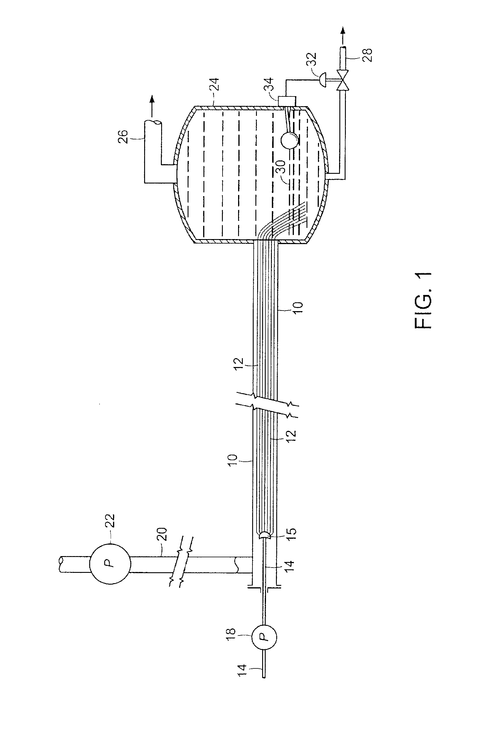
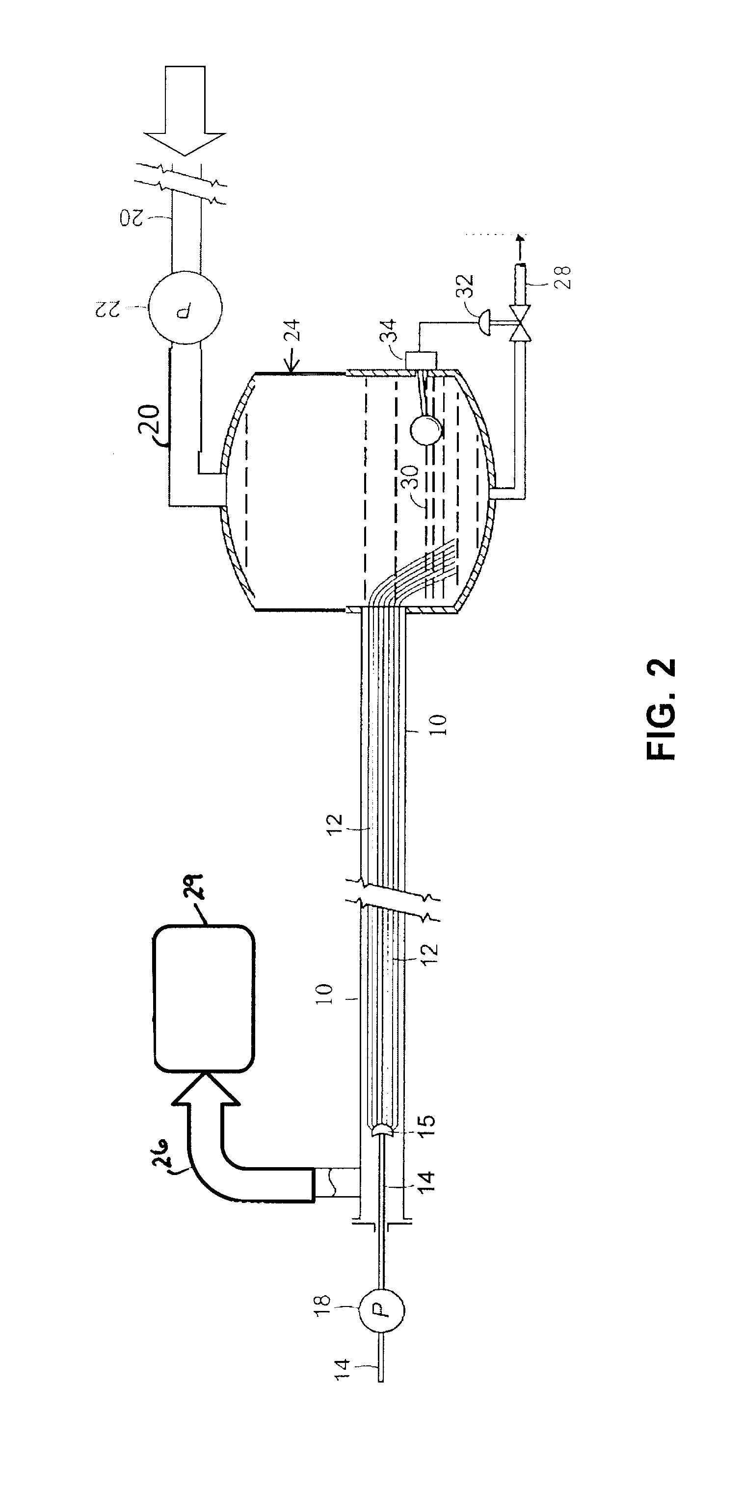
Processes are provided which utilize fiber conduit reactors / contactors to effect extraction of metal element / s, metal compound / s, metalloid element / s, and / or metalloid compound / s from a fluid stream. In particular, methods are provided which include introducing a first stream comprising an extractant and a second stream comprising a metal element, a metal compound, a metalloid element, and / or a metalloid compound into a conduit reactor proximate a plurality of fibers. The second stream is substantially immiscible with the first stream. The streams are introduced into the conduit reactor such that they are in contact and the extractant of the first stream interacts with the second stream to extract the metal element, a metal compound, a metalloid element, and / or a metalloid compound from the second stream into the first stream. The method further includes receiving the first and second streams in collection vessel / s and withdrawing separately the first and second streams from collection vessel / s.

Description

PRIORITY CLAIM[0001]The present application claims priority to U.S. Provisional Application No. 61 / 702,345 filed Sep. 18, 2012.BACKGROUND OF THE INVENTION[0002]1. Field of the Invention[0003]This invention generally relates to fiber conduit reactors / contactors, and specifically relates to processes utilizing such devices to effect extraction of metals and / or metalloids from fluidic streams.[0004]2. Description of the Related Art[0005]The following descriptions and examples are not admitted to be prior art by virtue of their inclusion within this section.[0006]Chemical extraction is desirable for a variety of reasons. In particular, many solids, liquids and gases contain contaminants which may hinder their further use and, thus, extraction of the contaminants is desirable. In addition or alternatively, many solids, liquids and gases contain valuable substances which are desirable to extract. Moreover, waste streams often contain pollutants which do not meet environmental regulations....

Claims


Application Information

Patent Timeline
Patent Type & Authority Applications(United States)
IPC IPC(8): B01D11/04C02F1/26
CPCC02F1/26B01D11/04C02F2101/103C02F2101/20C02F2101/308C02F2103/10C02F2103/24C02F2103/30C02F2103/325C07D207/06C07D333/76B01D11/0449C22B3/26Y02P10/20C02F2101/34C02F2103/343C07C29/76C07C51/47C07C67/56C07F9/09
Inventor MASSINGILL, JOHN LEE
Owner CHEMTOR LP
Learn More