Functionalized Carbon Electrode, Related Material, Process for Production, and Use Thereof

a carbon electrode and functional technology, applied in the manufacturing process of electrodes, cell components, impregnation manufacturing, etc., can solve the problems of increasing materials cost, limiting available storage capacity, increasing cost, etc., and achieves simple synthesis processing and low cost of raw materials.

Inactive Publication Date: 2014-04-24
SEYMOUR FRASER
View PDF0 Cites 91 Cited by
  • Summary
  • Abstract
  • Description
  • Claims
  • Application Information

AI Technical Summary

Benefits of technology

[0029]It is an advantage of the present invention that the electrode material provides low cost of raw materials and simple synthesis processing.
[0030]The aforementioned objects and advantages are satisfied by a porous carbon comprising at least one functionalizing agent, the incorporation of said functionalizing agent with said carbon material is one or more selected a group consisting of a dopant, a physical mixture composite carbon matrix, a deposit upon said carbon surface, or any combination thereof.
[0031]The electrode material not only is suitable as a material for EC and secondary batteries, but also may be used as primary battery electrodes, fuel cell electrodes, absorption electrodes in water de-ionization or gas purification, and as electrodes for electrolysis.
[0032]As used herein “substantially”, “generally”, “relatively”, “approximately”, and “about” are relative modifiers intended to indicate permissible variation from the characteristic so modified. It is not intended to be limited to the absolute value or characteristic, which it modifies but rather approaching or approximating such a physical or functional characteristic.
[0033]References to “one embodiment”, “an embodiment”, or “in embodiments” mean that the feature being referred to is included in at least one embodiment of the invention. Moreover, separate references to “one embodiment”, “an embodiment”, or “in embodiments” do not necessarily refer to the same embodiment; however, neither are such embodiments mutually exclusive, unless so stated, and except as will be readily apparent to those skilled in the art. Thus, the invention can include any variety of combinations and / or integrations of the embodiments described herein.
[0034]In the following description, reference is made to the accompanying drawings, which are shown by way of illustration to specific embodiments in which the invention may be practiced. The following illustrated embodiments are described in sufficient detail to enable those skilled in the art to practice the invention.

Problems solved by technology

These types of activated carbons suffer from a number of limitations: a) the smallest of the pores are not accessible to the ionic species in the electrolyte, and therefore do not contribute charge storage capacity; b) the pore size distribution of AC tends to not be hierarchical and thus does not provide electrolyte reservoirs within the electrode, which limits available storage capacity at high charge / discharge rates; c) the tortuous pore structure is not through-connected so the transport of electrolyte ions and evolved gas species is impeded; d) low apparent density limits volumetric energy; e) the activation involves an additional step in the manufacturing process which increases cost; f) the activation process itself decreases carbon yield, thereby further increasing materials cost; and g) these materials and methods do not inherently permit a means to dope the carbon matrix.
The materials and synthesis costs of these approaches are very high, however.
However, power density also is limited by the surface nature of pseudocapacitance as the longer ion diffusion length of thicker material serves to reduce reaction rate.
The power density of electrodes using these oxides is further limited by the very low intrinsic electronic conductivity of these materials.
While each of these approaches offer improved rate performance resulting from the reduced ion diffusion length vs. oxide powder based paste electrodes, they do not resolve the underlying problems associated with electronic conductivity and electrolyte accessibility.
While Long's approach does improve many of the shortcomings of the oxide as an EC electrode active material, it is limited to the formation of a MnO2 or iron oxide only film.
Also, the active material is limited to one or more metal oxides.
With U.S. Pat. No. 8,614,878, Seymour discloses an electrode material created by forming a thin conformal coating of one or more metal oxides on a carbon powder; however, the carbon is limited and the active material is limited to one or more metal oxides.
These expansion / contraction cycles cause the eventual breakdown of the oxide limiting device cycle life.

Method used


Image

  • Functionalized Carbon Electrode, Related Material, Process for Production, and Use Thereof
  • Functionalized Carbon Electrode, Related Material, Process for Production, and Use Thereof
  • Functionalized Carbon Electrode, Related Material, Process for Production, and Use Thereof

Examples


example i

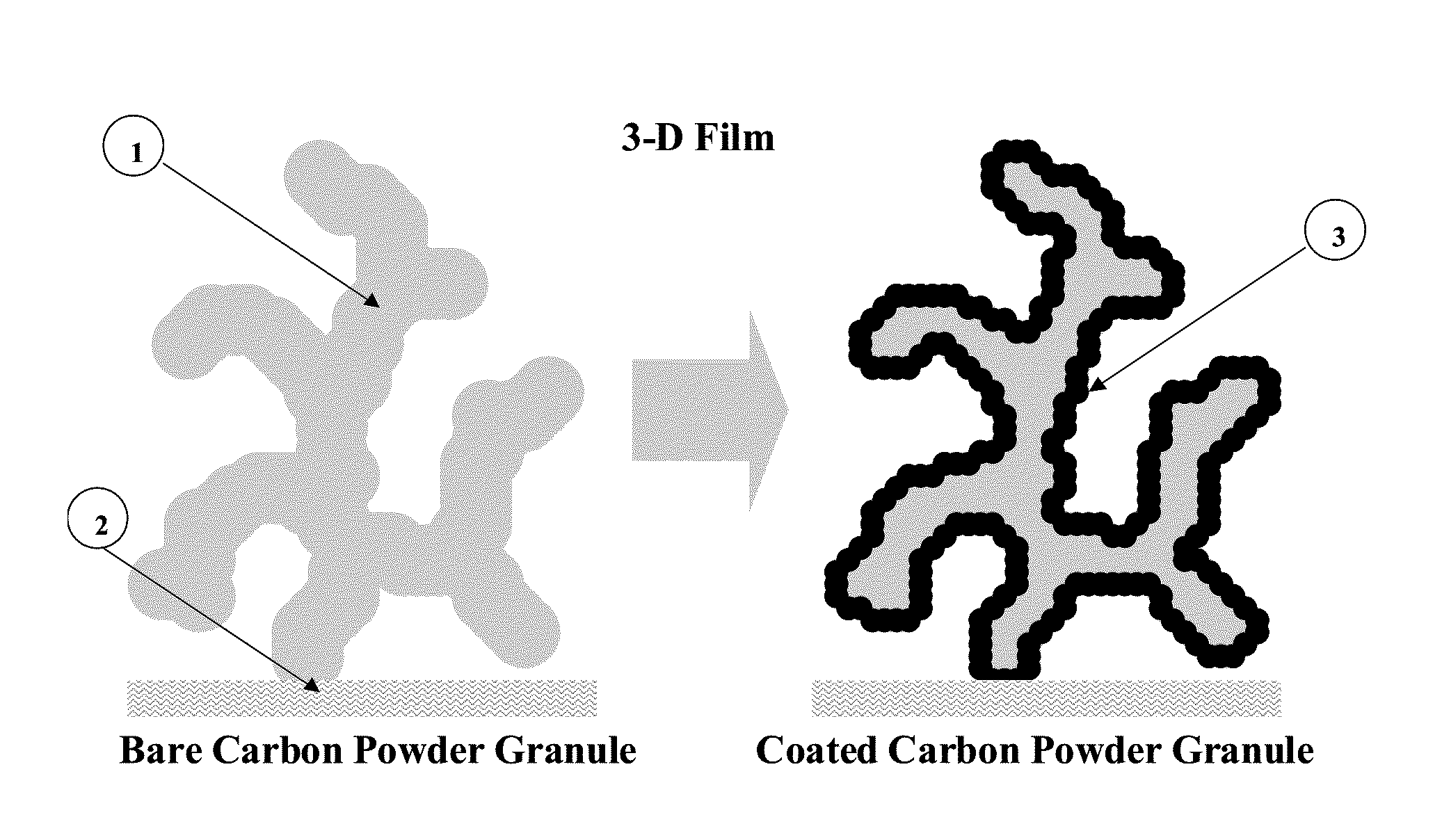
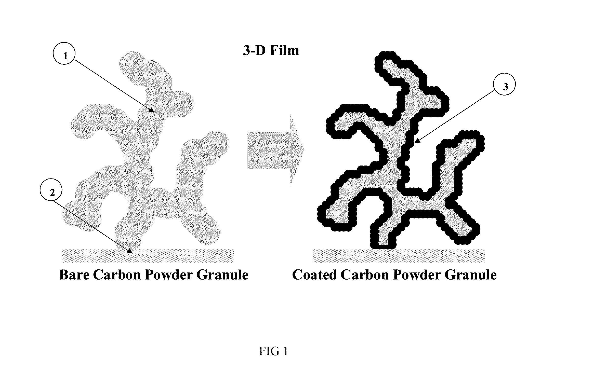
[0067]Fabrication of functionalized porous carbon electrode material; birnessite manganese / nickel oxide film on carbon nanofoam.

[0068]An electrode material as illustrated in FIG. 1 and FIG. 3 was formed by immersing a carbon structure for a controlled period of time in a solution comprising permanganate and nickel salts in a controlled ratio dissolved in ultra-pure water / pH buffer at a controlled pH and temperature. The manganese and nickel from the aqueous permanganate / nickel precursor solution are reduced on the surface of the carbon and co-deposited upon the carbon forming an insoluble oxide film.

[0069]Carbon aerogel was purchased from a commercial source (Marketech International Inc.) with an approximate thickness of 170 micrometers. Carbon aerogel paper was cut into pieces of approximately 1 centimeter by 1 centimeter and then soaked and vacuum saturated in purified water.

[0070]In this exemplary embodiment, the aqueous metal salt precursor solution comprised manganese / nickel mi...

example ii

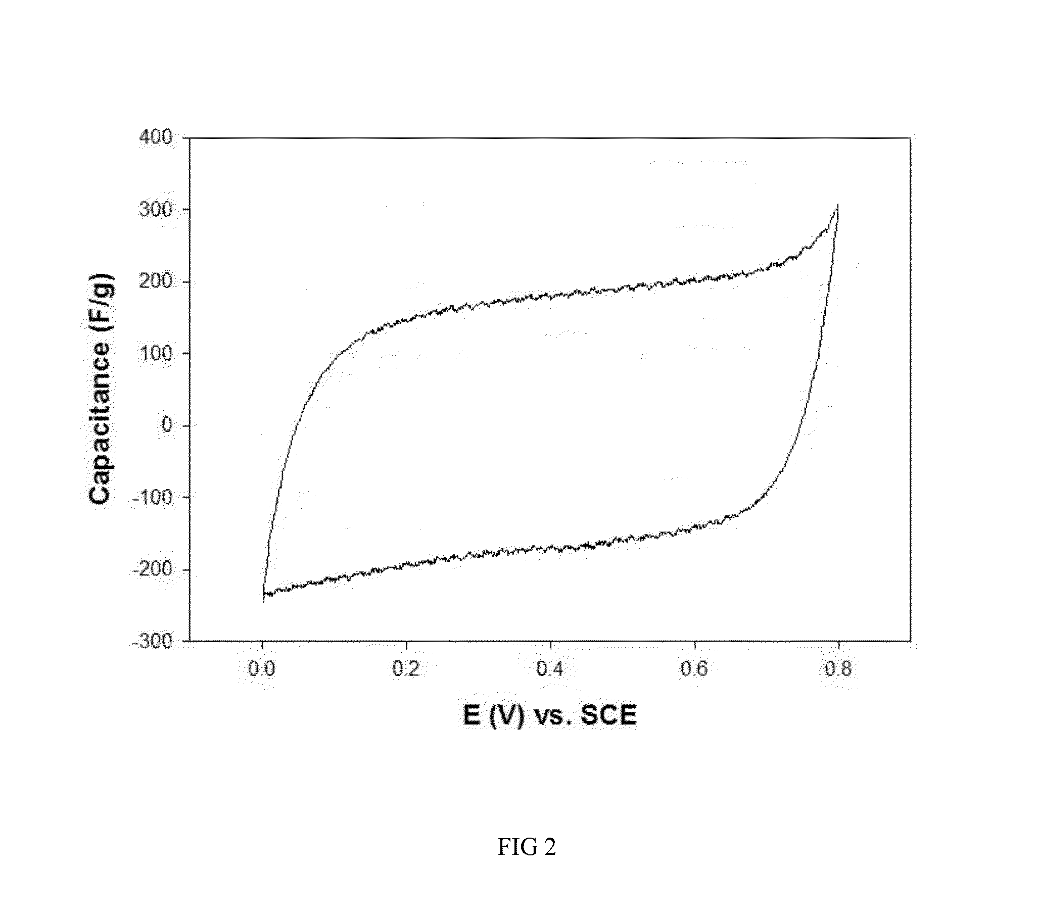
Characterization of electrode material; manganese / nickel oxide film on carbon aerogel

[0073]FIG. 2 shows cyclic voltammetry data of a 4:1 manganese / nickel oxide material with capacitance of approximately 180 F / g in 1M LiCl electrolyte.

example iii

[0074]Fabrication of functionalized porous carbon electrode material; nanoscale oxide film comprising spinel manganese doped with nickel on carbon aerogel.

[0075]An electrode material is formed as in EXAMPLE I, using a precursor ratio of about 0.99:0.01 manganese:nickel.

[0076]Prior to drying, counter ions are exchanged for lithium ions by immersion of the formed electrode in an aqueous solution bearing lithium ions such as lithium nitrate, lithium sulfate or lithium hydroxide, for example. In this exemplary embodiment, lithium nitrate was used. Such immersion is carried out first under vacuum equilibration, then at room temperature or elevated temperature or under microwave heating, for example. In this exemplary embodiment, about 30° C. for about 2-4 hours was used.

[0077]The material was subsequently heated to about 300-350° C. under nitrogen atmosphere for about 1-2 hours, followed by heating at about 200-220° C. in air for about 3-6 hours.


PUM

PropertyMeasurementUnit
particle sizeaaaaaaaaaa
specific surface areaaaaaaaaaaa

Abstract

The present invention relates to a material for use as an electrode for electrochemical energy storage devices such as electrochemical capacitors (ECs) and secondary batteries, primary batteries, metal / air batteries, fuel cells, flow batteries and a method for producing the same. More specifically, this invention relates to an electrode material consisting of a functionalized porous carbon, a method for producing the same, and an energy storage device using said electrode materials.

Description

CROSS-REFERENCE TO RELATED APPLICATIONS[0001]This application is a continuation-in-part of U.S. applications identified by application No. 61 / 756,508 filed on Jan. 25, 2013, by application Ser. No. 13 / 190,006 filed on Jul. 25, 2011, and claims priority thereto; the foregoing applications being incorporated herein by reference.FIELD OF THE INVENTION[0002]The present invention relates to a material for use as an electrode for electrochemical energy storage devices such as electrochemical capacitors (ECs) and secondary batteries, primary batteries, metal / air batteries, fuel cells, flow batteries and a method for producing the same. More specifically, this invention relates to an electrode material consisting of a functionalized porous carbon, a method for producing the same, and an energy storage device using said electrode materials.BACKGROUND OF THE INVENTION[0003]Electrochemical capacitors (EC, sometimes referred to in the art as ultra-capacitors, super-capacitors or pseudo-capacito...

Claims


Application Information

Patent Timeline
Patent Type & Authority Applications(United States)
IPC IPC(8): H01G11/38H01M4/36
CPCH01M4/366H01G11/38Y02E60/13H01G11/36H01G11/42H01G11/46H01M4/0416H01M4/131H01M4/1391H01M4/48H01M4/50H01M4/52H01M4/625H01G11/24Y02E60/10
Inventor SEYMOUR, FRASER
Owner SEYMOUR FRASER
Why Eureka
Try Eureka