Method And A Control System For Controlling A Melting Process

Active Publication Date: 2014-05-15
ABB (SCHWEIZ) AG
View PDF0 Cites 9 Cited by
  • Summary
  • Abstract
  • Description
  • Claims
  • Application Information

AI Technical Summary

Benefits of technology

[0009]It is an object of the present disclosure to reduce the EAF total cycle time and to increase the yield of iron. Thereby the electrode and stirrer

Problems solved by technology

It consumes a large amount of electrical and chemical energy.
A modern EAF produces over 300 tapping tons of steel pear heat, and since the prod

Method used


Image

  • Method And A Control System For Controlling A Melting Process
  • Method And A Control System For Controlling A Melting Process
  • Method And A Control System For Controlling A Melting Process

Examples


Example

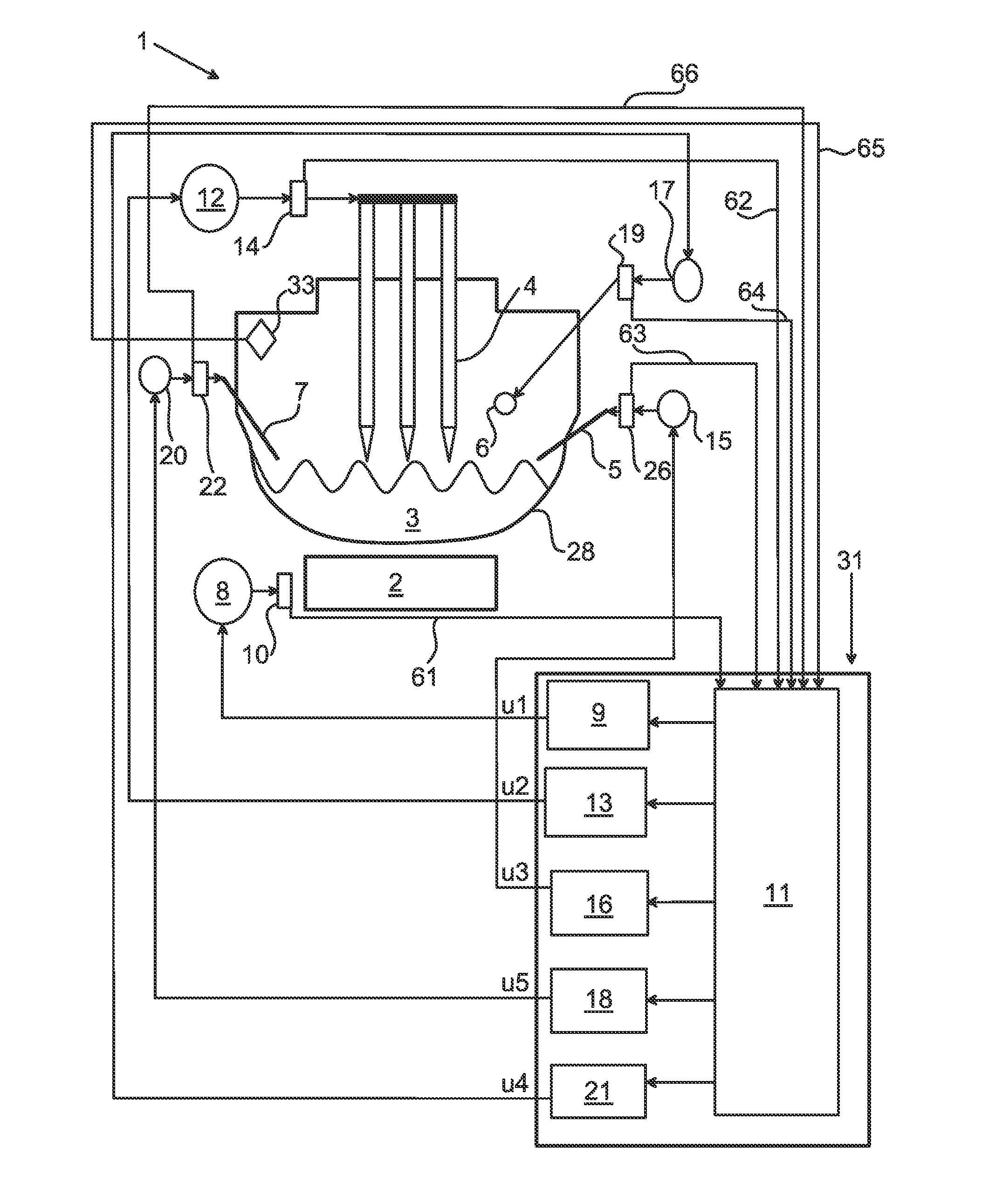
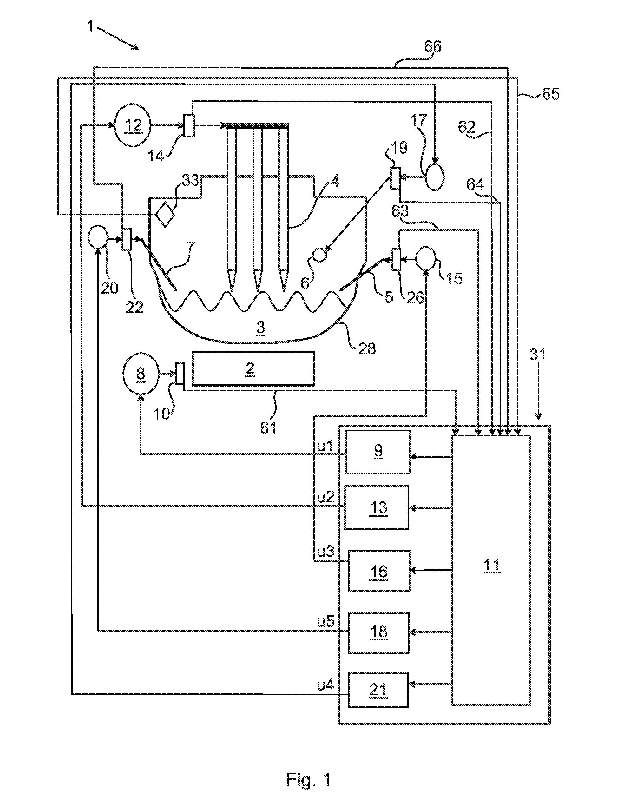
[0043]FIG. 1 illustrates an electrical arc furnace (the EAF may be a DC EAF or an AC EAF and is hereinafter called EAF) arranged for melting metallic material such as scrap being loaded into the EAF prior to the beginning of the melting process. The EAF further comprises one or more electrodes, a vessel covered with a retractable roof through which the one or more graphite electrodes enter the furnace and a power supply system operatively connected to the electrodes. At least one apparatus for electromagnetic stirring (hereinafter called stirrer) of molten metal in the EAF 1 is arranged on an outer surface, preferably the bottom surface, of the EAF vessel.

[0044]A power supply system is operatively connected to the stirrer. The power supply system operatively connected to the electrodes and the power supply system operatively connected to the stirrer may be two separate power supply systems, but it can also be the same system for both purposes. At least one control unit, including ha...


PUM

PropertyMeasurementUnit
Temperatureaaaaaaaaaa
Poweraaaaaaaaaa
Flow rateaaaaaaaaaa

Abstract

A method of controlling a melting process in an electric arc furnace for melting a metallic material. By means of the present disclosure it is possible to minimize desired process properties such as the melting time or the total power consumption of the melting process. The method includes the steps of receiving or collecting measured data of at least one process variable, determining the current state of the process, performing an optimization of the melting process, determining a process input based on the result of the optimization, and controlling the melting process by means of the process input. A control system is also presented herein.

Description

FIELD OF THE INVENTION[0001]The present invention relates to a method and a control system for controlling a melting process in an electric arc furnace (EAF) comprising one or more electrodes for melting metal or metal alloys and an electromagnetic stirrer (EMS) for stirring the melt.BACKGROUND OF THE INVENTION[0002]Electric arc furnace (EAF) steelmaking is a highly energy-intensive industrial process. It consumes a large amount of electrical and chemical energy. A modern EAF produces over 300 tapping tons of steel pear heat, and since the production of steel in an EAF requires a huge amount of electrical and chemical energy, the energy cost for one such furnace annually is very high. This is the reason why the latest EAF technology development has been mainly focused on reducing the energy consumption (electricity and oxygen) and thereby increasing the productivity. Also from an environmental point of view there is a desire to reduce the emissions of carbon dioxide and other emissi...

Claims


Application Information

Patent Timeline
IPC IPC(8): F27D19/00
CPCF27D19/00C21C5/5211F27D21/00F27D27/00H05B7/148C21C2005/5288C21C2300/06F27B3/28C21C5/5217Y02P10/20Y02P10/25H05B7/144H05B7/18
Inventor LUNDH, MICHAELZHANG, XIAOJING
Owner ABB (SCHWEIZ) AG
Why Eureka
Try Eureka