Blend polymeric membranes containing fluorinated ethylene-propylene polymers for gas separations

a technology of ethylenepropylene polymer and blend membrane, which is applied in the field of polymeric blend membranes containing fluorinated ethylenepropylene polymers, can solve the problems of complicated and tedious to make such asymmetric integral skinned membranes, and reducing the selectivity of membranes, etc., to achieve low environmental hazard potential, low toxicity, and low corrosion activity

Inactive Publication Date: 2014-05-22
UOP LLC
View PDF7 Cites 7 Cited by
  • Summary
  • Abstract
  • Description
  • Claims
  • Application Information

AI Technical Summary

Benefits of technology

[0010]The solvents used for dissolving the fluorinated ethylene-propylene polymer and the second polymer different from the fluorinated ethylene-propylene polymer are chosen primarily for their ability to completely dissolve the polymers and for ease of solvent removal in the membrane formation steps. Other considerations in the selection of solvents include low toxicity, low corrosive activity, low environmental hazard potential, availability and cost. Representative solvents for use in this invention include typical solvents used for the formation of polymeric membranes, such as acetone, tetrahydrofuran (THF), ethyl acetate, methyl acetate, 1-methyl-2-pyrrolidone (NMP) and N,N-dimethyl acetamide (DMAC), methylene chloride, N,N-dimethylformamide (DMF), dimethyl sulfoxide (DMSO), 1,1,1,-trifluoro-3,3-difluorobutane, toluene, α,α,α-trifluorotoluene, dioxanes, 1,3-dioxolane, mixtures thereof, others known to those skilled in the art and mixtures thereof.

Problems solved by technology

Although CA membranes have many advantages, they are limited in a number of properties including selectivity, permeability, and in chemical, thermal, and mechanical stability.
However, it is very complicated and tedious to make such asymmetric integrally skinned membranes having a defect-free skin layer.
The presence of nanopores or defects in the skin layer reduces the membrane selectivity.
Fabrication of TFC membranes that are defect-free is also difficult, and requires multiple steps.
The coating of such coated membranes, however, is subject to swelling by solvents, poor performance durability, low resistance to hydrocarbon contaminants, and low resistance to plasticization by the sorbed penetrant molecules such as CO2 or C3H6.

Method used


Image

  • Blend polymeric membranes containing fluorinated ethylene-propylene polymers for gas separations
  • Blend polymeric membranes containing fluorinated ethylene-propylene polymers for gas separations

Examples


example 1

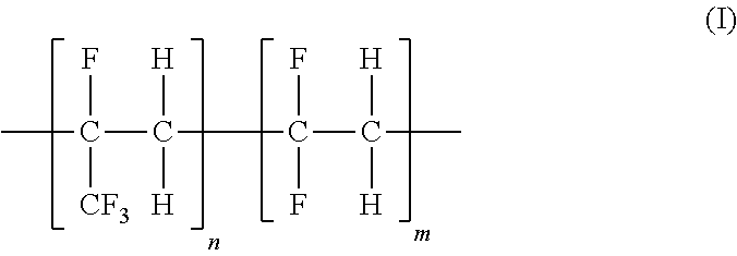
Synthesis of 2,3,3,3-tetrafluoropropene / vinylidene fluoride Copolymer Comprising about 90 mol % 2,3,3,3-tetrafluoropropene-based Structural Units and About 10 mol % vinylidene fluoride-based Structural Units (Abbreviated as PTFP-PVDF-90-10)

[0036]Into 100 mL of degassed deionized water with stirring, 2.112 g of Na2HPO4.7H2O, 0.574 g of NaH2PO4, and 2.014 g of C7F15CO2NH4 were added. 0.3068 g of (NH4)2S2O8 was added into above aqueous solution with stirring and nitrogen bubbling. The obtained aqueous solution was immediately transferred into an evacuated 300 mL autoclave reactor through a syringe. The reactor was cooled with dry ice while the aqueous solution inside was slowly stirred. When the internal temperature decreased to about 0° C., the transfer of a mixture of 2,3,3,3-tetrafluoropropene (111.3 g) and vinylidene fluoride (11.8 g) was started. At the end of the transfer, the internal temperature was below about −5° C. The dry ice cooling was removed. The autoclave reactor was s...

example 2

Synthesis of 2,3,3,3-tetrafluoropropene / vinylidene fluoride Copolymer Comprising About 64 mol % 2,3,3,3-tetrafluoropropene-based Structural Units and About 36 mol % vinylidene fluoride-based Structural Units (Abbreviated as PTFP-PVDF-64-36)

[0040]Into 100 mL of degassed deionized water with stirring, 2.112 g of Na2HPO4.7H2O, 0.574 g of NaH2PO4, and 2.014 g of C7F15CO2NH4 were added. 0.3018 g of (NH4)2S2O8 was added into above aqueous solution with stirring and nitrogen bubbling. The obtained aqueous solution was immediately transferred into an evacuated 300 mL autoclave reactor through a syringe. The autoclave reactor was cooled with dry ice and the aqueous solution inside was slowly stirred. When the internal temperature decreased to about 0° C., the transfer of a mixture containing 77.1 g of 2,3,3,3-tetrafluoropropene and 32.3 g of vinylidene fluoride into the autoclave reactor was started. At the end of the transfer, the internal temperature was below about −5° C. The dry ice cool...

example 3

Synthesis of 2,3,3,3-tetrafluoropropene / vinylidene fluoride Copolymer Comprising About 22 mol % 2,3,3,3-tetrafluoropropene-based Structural Units and About 78 mol % vinylidene fluoride-based Structural Units (Abbreviated as PTFP-PVDF-22-78)

[0044]Into 100 mL of degassed deionized water with stirring, 2.153 g of Na2HPO4.7H2O, 0.568 g of NaH2PO4, and 2.048 g of C7F15CO2NH4 were added. 0.2598 g of (NH4)2S2O8 was added into above aqueous solution with stirring and nitrogen bubbling. The obtained aqueous solution was immediately transferred into an evacuated 300 mL autoclave reactor through a syringe. The autoclave reactor was cooled with dry ice and the aqueous solution inside was slowly stirred at 50 rpm. When the internal temperature decreased to about −4° C., a mixture containing 47.7 g of 2,3,3,3-tetrafluoropropene and 45.8 g of vinylidene fluoride was transferred into the autoclave reactor. The dry ice cooling was removed. The autoclave reactor was slowly warmed up by air. The aqueo...


PUM

PropertyMeasurementUnit
mol %aaaaaaaaaa
mol %aaaaaaaaaa
mol %aaaaaaaaaa

Abstract

The present invention generally relates to gas separation membranes and, in particular, to high selectivity fluorinated ethylene-propylene polymer-comprising polymeric blend membranes for gas separations. The polymeric blend membrane comprises a fluorinated ethylene-propylene polymer and a second polymer different from the fluorinated ethylene-propylene polymer. The fluorinated ethylene-propylene polymers in the current invention are copolymers comprising 10 to 99 mol % 2,3,3,3-tetrafluoropropene-based structural units and 1 to 90 mol % vinylidene fluoride-based structural units. The second polymer different from the fluorinated ethylene-propylene polymer is selected from a low cost, easily processable glassy polymer.

Description

FIELD OF THE INVENTION[0001]This invention relates to polymeric blend membranes containing fluorinated ethylene-propylene polymers. These membranes have high selectivities for gas separations and have particular use in natural gas upgrading.BACKGROUND OF THE INVENTION[0002]In the past 30-35 years, the state of the art of polymer membrane-based gas separation processes has evolved rapidly. Membrane-based technologies are a low capital cost solution and provide high energy efficiency compared to conventional separation methods. Membrane gas separation is of special interest to petroleum producers and refiners, chemical companies, and industrial gas suppliers. Several applications of membrane gas separation have achieved commercial success, including N2 enrichment from air, carbon dioxide removal from natural gas and from enhanced oil recovery, and also in hydrogen removal from nitrogen, methane, and argon in ammonia purge gas streams. For example, UOP's Separex™ cellulose acetate spir...

Claims


Application Information

Patent Timeline
Patent Type & Authority Applications(United States)
IPC IPC(8): B01D71/32B01D53/22B01D61/00
CPCB01D53/22B01D67/0011C02F1/441C10G31/00B01D2256/24B01D2257/102B01D2257/104B01D2257/108B01D2257/11B01D2257/304B01D2257/504B01D2257/708B01D2258/0283C10L3/102C10L3/106C10G5/00C02F2101/34B01D71/32B01D53/228Y02C20/40B01D67/00111
Inventor LIU, CHUNQINGOSMAN, ZARALU, CHANGQINGPOSS, ANDREW J.SINGH, RAJIV R.
Owner UOP LLC
Why Eureka
Try Eureka