Novel method and product
a lithium insertion material and cathode technology, applied in the direction of inorganic chemistry, conductive materials, silicates, etc., can solve the problem of poor conductivity of polyanion materials
- Summary
- Abstract
- Description
- Claims
- Application Information
AI Technical Summary
Benefits of technology
Problems solved by technology
Method used
Image
Examples
example 1
[0031]All starting materials used were of 99.99% purity. Li2FeSiO4 / C samples were prepared by the so-called combustion method using LiNO3 (Sigma-Aldrich) and Fe(NO3)3.9H2O (Sigma-Aldrich) as the oxidant precursors, sucrose (Sigma-Aldrich) as fuel and fumed SiO2 nanoparticles (Sigma-Aldrich). Typically, the reaction can be described as follows:
48LiNO3+24Fe (NO3)3+24SiO2+13C12H22O11→24Li2FeSiO4+60N2+156CO2+144H2O
[0032]Briefly, the preset stoichiometric amounts of reagent grade Li, Fe and Si sources were dissolved (or, in the case of fumed SiO2, suspended and / or dispersed) in at least the minimum amount of distilled water; the dissolved fuel (sucrose) was then added to the solution. The beaker containing the reaction mixture was placed on an electric heater and kept at 120° C. for 2 hours to evaporate the excess water. The liquid adopted a syrup consistency and the colour changed from red to green while the syrup swelled up and transformed into brown foam. On continuing heating, this f...
example 2
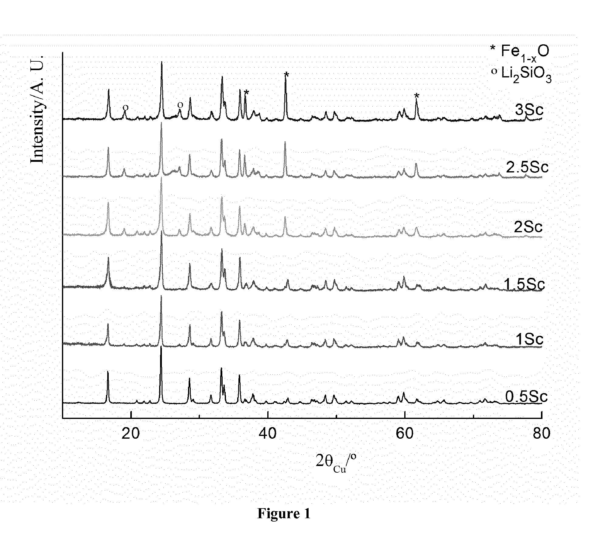
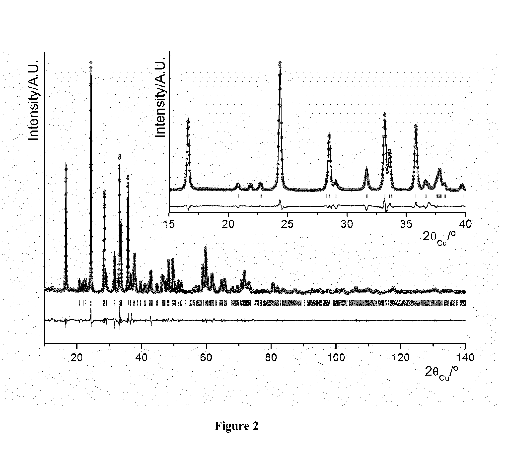
[0034]All samples were characterized by X-ray diffraction (XRD) using a Siemens D5000 diffractometer with Cu Kα radiation. The diffraction patterns were recorded in [10-120]° (2θ) angular range, using a 0.02° (2θ) step and a constant counting time of 10s. The lattice parameters and cation distributions were refined by the Rietveld method using the Fullprof program (J. Rodriguez-Carvajal, Fullprof, Program for Rietveld Refinement, version 3.7, LLB JRC (1997)). X-ray diffraction patterns of Li2FeSiO4 / C composites (0.5Sc, 1Sc, 1.5Sc, 2Sc, 2.5Sc and 3Sc) are compared in FIG. 1. Diffraction peaks can be indexed in a monoclinic cell (P2f / n space group) with the cell parameters a=8.2275(3) Å, b=5.0176 (2) Å, c=8.2313(2) Å, and β=99.1308(3) (see Table 1). A comparison of the diffraction patterns for the Li2FeSiO4 / C composites with various amounts of sucrose also showed that increasing sucrose content may lead to increasing Fe1-xO and Li2SiO3 impurities.
TABLE 1Comparison of cell parameters o...
example 3
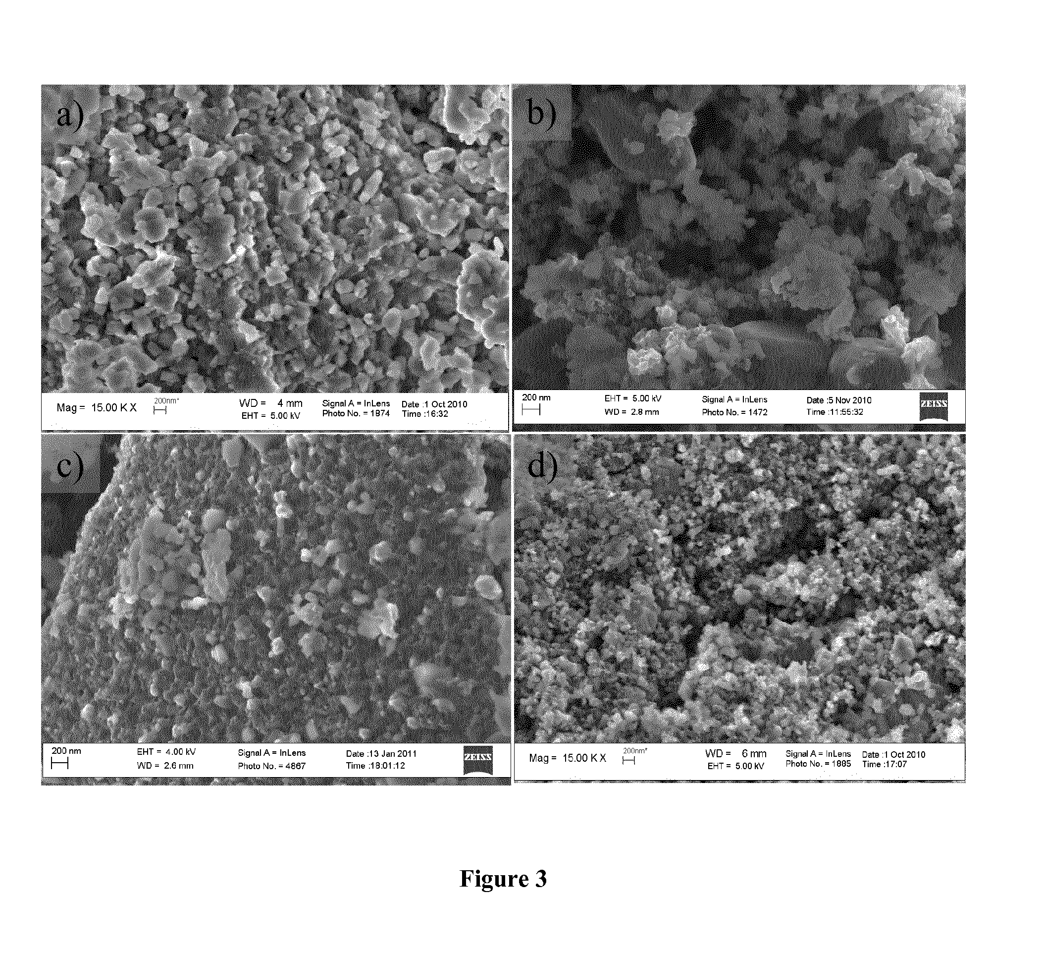
[0038]High Resolution Scanning Electron Microscopy was used to check trends in powder grain size and morphology with increasing sucrose amount. A high resolution scanning electron microscope (HRSEM LEO 1550) was used. FIG. 3 gives a comparison of SEM micrographs obtained for the Li2FeSiO4 / C materials with various amount of sucrose (0.5Sc, 1.5Sc, 2Sc and 3Sc). In samples prepared with a low amount of sucrose (0.5Sc), there was a greater extent of aggregation of prticles, and a larger particle size distribution. By increasing the amount of sucrose, a significant decrease in particle size and a more uniform particle size distribution is observed. The crystallite size, the specific surface area and carbon content of all samples were also estimated by XRD, BET method and TGA study, respectively. Specific surface area measurements were carried out by the Brunauer, Emmet and Teller (BET) method with a Micrometrics ASAP 2020 Accelerated Surface Area and Porosimetry Analyzer. Samples were dr...
PUM
| Property | Measurement | Unit |
|---|---|---|
| temperature | aaaaa | aaaaa |
| size | aaaaa | aaaaa |
| crystallite size | aaaaa | aaaaa |
Abstract
Description
Claims
Application Information
 - R&D
- Intellectual Property
- Life Sciences
- Materials
- Tech Scout
- Unparalleled Data Quality
- Higher Quality Content
- 60% Fewer Hallucinations
Browse by: Latest US Patents, China's latest patents, Technical Efficacy Thesaurus, Application Domain, Technology Topic, Popular Technical Reports.
© 2025 PatSnap. All rights reserved.Legal|Privacy policy|Modern Slavery Act Transparency Statement|Sitemap|About US| Contact US: help@patsnap.com


