
Molten salt battery

a molten salt battery and molten salt technology, applied in the field can solve the problems of increased cost of molten salt batteries, and deterioration of the positive electrode, and achieve the effect of lowering the operating temperatur

Inactive Publication Date: 2014-06-19
SUMITOMO ELECTRIC IND LTD +1
View PDF15 Cites 10 Cited by
  • Summary
  • Abstract
  • Description
  • Claims
  • Application Information

AI Technical Summary

Benefits of technology

The technical effect of this patent is to create a molten-salt battery that can operate at a lower temperature without damaging the positive electrode. The battery uses a special electrolyte made of cations that doesn't harm the material that makes the battery work.

Problems solved by technology

Thereby, the crystal structure of the positive-electrode active material is changed, and the positive electrode may be deteriorated.
When a mixed salt of sodium salt and cesium salt is used, the cesium ion may also cause deterioration of the positive electrode.
In addition, because cesium is expensive due to its scarcity, the use of cesium increases the cost of the molten-salt battery.

Method used


Image

  • Molten salt battery
  • Molten salt battery
  • Molten salt battery

Examples


embodiments

[0052]Subsequently, embodiments will be more specifically explained with reference to the following first to fifth embodiments.

first embodiment

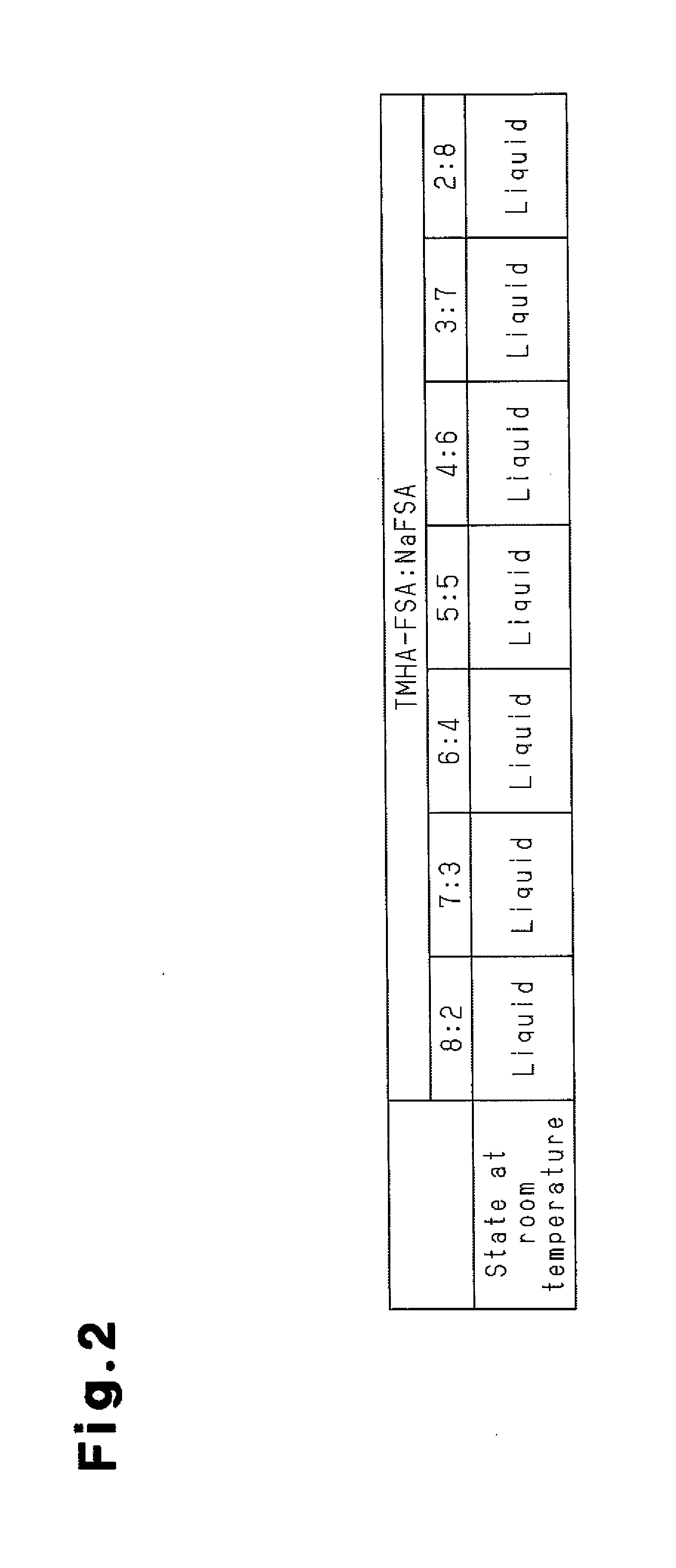
[0053]As a molten salt, a mixed salt of TMHA-FSA and NaFSA was prepared. Then states of the mixed salt at room temperature were investigated in relation to the molar ratios of the TMHA-FSA and the NaFSA in the mixed salt. First, a TMHA-Br produced by Wako Pure Chemical Industries, Ltd. and a KFSA produced by Mitsubishi Materials Electronic Chemicals Co., Ltd. were mixed in an equimolar ratio in water for preparing a TMHA-FSA. Then a resulting precipitate was filtrated and washed with water repeatedly several times. Subsequently, the TMHA-FSA was prepared by vacuum drying at 80° C. It should be noted that Br is bromine and K is potassium. The prepared TMHA-FSA and a NaFSA produced by Mitsubishi Materials Electronic Chemicals Co., Ltd. were mixed in various molar ratios in a glove box under an argon atmosphere to investigate its melting behavior at room temperature.

[0054]FIG. 2 is a table that represents molar ratios in the mixed salts of TMHA-FSA and NaFSA, and states of the mixed sa...

second embodiment

[0055]As a molten salt, a mixed salt of EMI-FSA and NaFSA was prepared. Then states of the mixed salt at room temperature were investigated in relation to the molar ratios of the EMI-FSA and the NaFSA in the mixed salt. The EMI-FSA was obtained from Tokyo Chemical Industry Co., Ltd. The EMI-FSA and a NaFSA produced by Mitsubishi Materials Electronic Chemicals Co., Ltd. were mixed in various molar ratios in the glove box under the argon atmosphere to investigate its melting behavior at room temperature.

[0056]FIG. 3 is a table that represents molar ratios in the mixed salts of EMI-FSA and NaFSA, and states of the mixed salts in each molar ratio at room temperature. As shown in FIG. 3, seven mixed salts that the molar ratios of the EMI-FSA and the NaFSA (EMI-FSA:NaFSA) were respectively 8:2, 7:3, 6:4, 5:5, 4:6, 3:7 and 2:8 were prepared. The mixed salts that the molar ratios were respectively 8:2 and 7:3 were liquid at room temperature. In addition, the mixed salts of other molar ratio...


PUM


Abstract

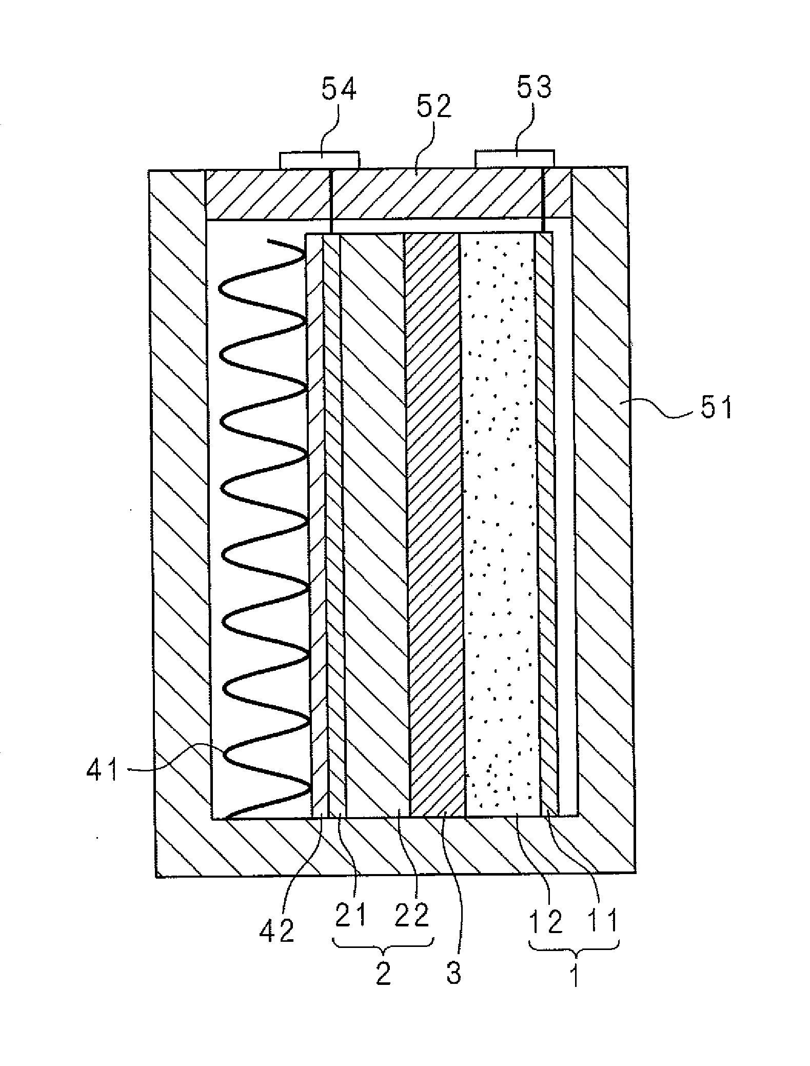
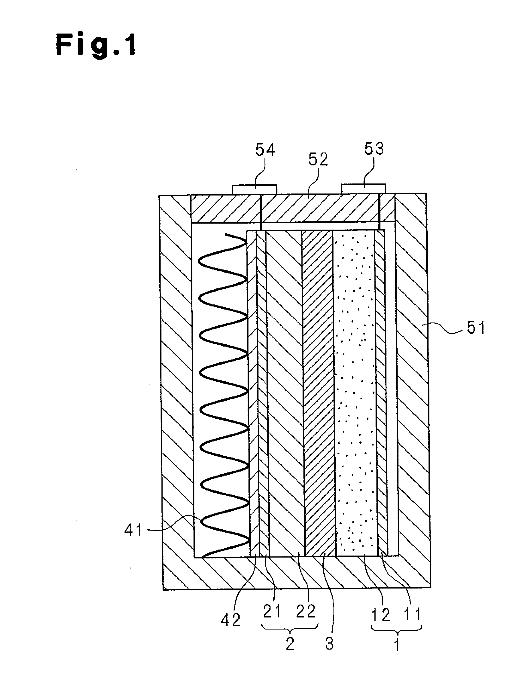
A separator (3) of a molten salt battery is impregnated with a molten salt that serves as the electrolyte. The molten salt contains, as cations, at least one kind of ions selected from among quaternary ammonium ions, imidazolium ions, imidazolinium ions, pyridinium ions, pyrrolidinium ions, piperidinium ions, morpholinium ions, phosphonium ions, piperazinium ions and sulfonium ions in addition to sodium ions. These cations do not have adverse effects on a positive electrode (1). In addition, the melting point of the molten salt, which contains sodium ions and the above-mentioned cations, is significantly lower than the operating temperature of sodium-sulfur batteries, said operating temperature being 280-360 DEG C. Consequently, the molten salt battery is capable of operating at lower temperatures than sodium-sulfur batteries.

Description

FIELD OF THE INVENTION[0001]The present invention relates to a molten-salt battery using a molten salt as an electrolyte.BACKGROUND OF THE INVENTION[0002]Utilization of natural energy such as solar power or wind power has been recently promoted. In power generation by natural energy, the amount of power generation is likely to be changed due to the effects of weather conditions or the like. For this reason, the power supply should be leveled by charge / discharge using a storage battery for supplying generated power. That is, a storage battery having high energy density and high efficiency is essential in promoting utilization of natural energy. Such storage batteries include a sodium-sulfur battery disclosed in Patent Document 1. In the sodium-sulfur battery, sodium ions are used as conducting ions. Other storage batteries having high energy density and high efficiency include a molten-salt battery.[0003]Molten-salt batteries are batteries using molten salts as electrolytes and opera...

Claims


Application Information

Patent Timeline
IPC IPC(8): H01M10/39
CPCH01M10/399H01M2300/0048Y02E60/10H01M10/39H01M10/0568H01M10/054H01M4/485
Inventor NITTA, KOJIINAZAWA, SHINJIMAJIMA, MASATOSHIYAMAGUCHI, ATSUSHISAKAI, SHOICHIROFUKUNAGA, ATSUSHIHAGIWARA, RIKANOHIRA, TOSHIYUKIMATSUMOTO, KAZUHIKO
Owner SUMITOMO ELECTRIC IND LTD
Learn More