
Protected lithium electrodes having a porous electrolyte interlayer and associated battery cells

a technology of protective lithium electrodes and electrolyte interlayers, which is applied in the direction of cell components, cell component details, electrochemical generators, etc., can solve the problems of rechargeable lithium metal batteries failing, battery short circuit, and no rechargeable lithium metal batteries have yet succeeded in the market pla

Active Publication Date: 2014-06-19
POLYPLUS BATTERY CO INC
View PDF0 Cites 106 Cited by
  • Summary
  • Abstract
  • Description
  • Claims
  • Application Information

AI Technical Summary

Benefits of technology

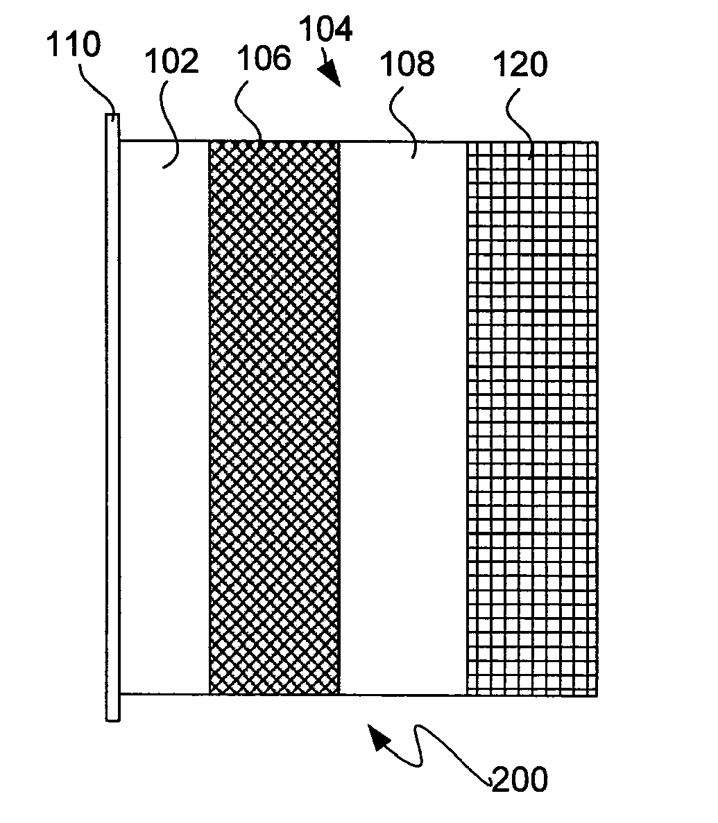
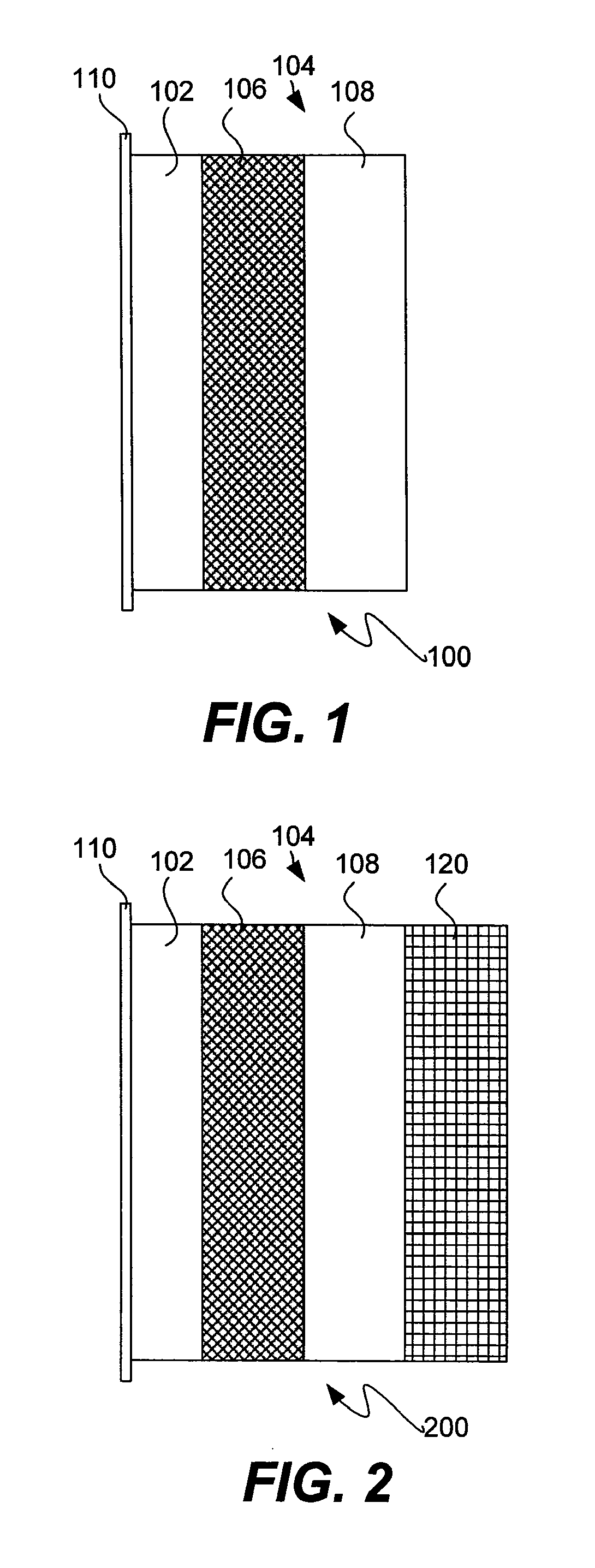
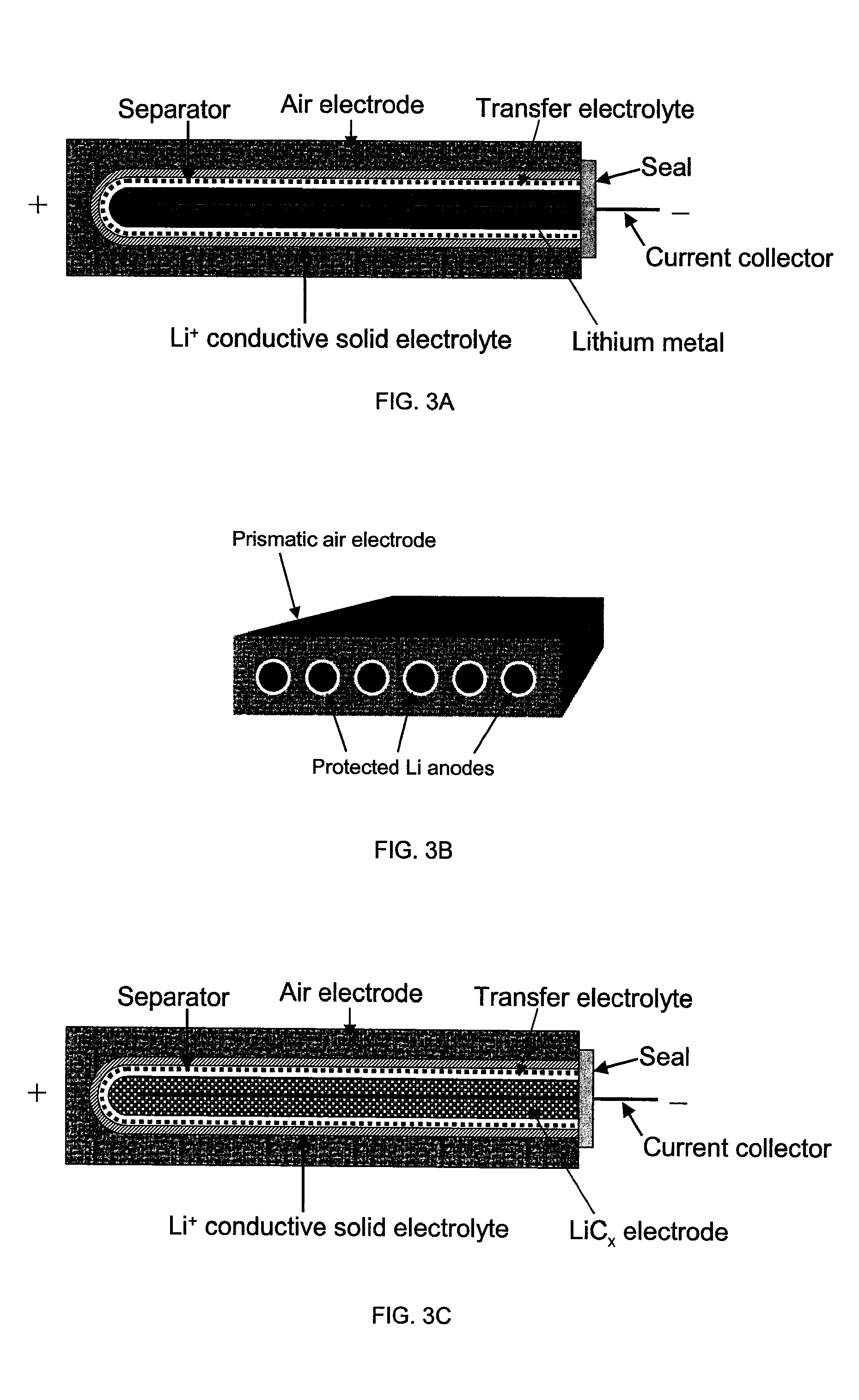
The present invention is about creating protective architectures for active metal electrochemical devices, such as lithium-based batteries. These architectures prevent the metal from reacting with the environment on the other side of a porous separator, which can be highly corrosive. This results in effective isolation of the anode from the cathode, allowing for ion transport while preventing deleterious reactions. The invention can be applied to various battery cell configurations and compositions, including aqueous, air, metal hydride and metal oxide cathodes, as well as aqueous, organic or ionic liquid catholytes. The invention also includes electrolyte compositions to enhance battery safety and performance.

Problems solved by technology

Unfortunately, no rechargeable lithium metal batteries have yet succeeded in the market place.
The failure of rechargeable lithium metal batteries is largely due to cell cycling problems.
This causes an internal short circuit in the battery, rendering the battery unusable after a relatively few cycles.
While cycling, lithium electrodes may also grow “mossy” deposits that can dislodge from the negative electrode and thereby reduce the battery's capacity.
Many techniques for applying protective layers have not succeeded.
Thus, they fail to adequately protect the lithium electrode.
In all cases however, there was substantial reaction of the alkali metal electrode with water.
In this regard, the prior art teaches that the use of aqueous cathodes or electrolytes with Li-metal anodes is not possible since the breakdown voltage for water is about 1.2 V and a Li / water cell can have a voltage of about 3.0 V. Direct contact between lithium metal and aqueous solutions results in violent parasitic chemical reaction and corrosion of the lithium electrode for no useful purpose.

Method used


Image

  • Protected lithium electrodes having a porous electrolyte interlayer and associated battery cells
  • Protected lithium electrodes having a porous electrolyte interlayer and associated battery cells
  • Protected lithium electrodes having a porous electrolyte interlayer and associated battery cells

Examples


example 1

Li / Seawater Cell

[0154]A series of experiments was performed in which the commercial ionically conductive glass-ceramic from OHARA Corporation was used as a membrane separating aqueous catholyte and non-aqueous anolyte. The cell structure was Li / non-aqueous electrolyte / glass-ceramic / aqueous electrolyte / Pt. A lithium foil from Chemetall Foote Corporation with thickness of 125 microns was used as the anode. The GLASS-CERAMIC plates were in the range of 0.3 to 0.48 mm in thickness. The GLASS-CERAMIC plate was fitted into an electrochemical cell by use of two o-rings such that the GLASS-CERAMIC plate was exposed to an aqueous environment from one side and a non-aqueous environment from the other side. In this case, the aqueous electrolyte comprised an artificial seawater prepared with 35 ppt of “Instant Ocean” from Aquarium Systems, Inc. The conductivity of the seawater was determined to be 4.5 10−2 S / cm. A microporous Celgard separator placed on the other side of the GLASS-CERAMIC was f...

example 2

Li / Air Cell

[0155]The cell structure was similar to that in the previous example, but instead of a Pt electrode completely immersed in the electrolyte, this experimental cell had an air electrode made for commercial Zn / Air batteries. An aqueous electrolyte used was 1 M LiOH. A Li anode and a non-aqueous electrolyte were the same as described in the previous example.

[0156]An open circuit potential of 3.2 V was observed for this cell. FIG. 5 shows discharge voltage-time curve at discharge rate of 0.3 mA / cm2. The cell exhibited discharge voltage of 2.8-2.9 V. for more than 14 hrs. This result shows that good performance can be achieved for Li / air cells with solid electrolyte membrane separating aqueous catholyte and non-aqueous anolyte.

example 3

Li-Ion Cell

[0157]In these experiments the commercial ionically conductive glass-ceramic from OHARA Corporation was used as a membrane separating aqueous catholyte and non-aqueous anolyte. The cell structure was carbon / non-aqueous electrolyte / glass-ceramic plate / aqueous electrolyte / Pt. A commercial carbon electrode on copper substrate comprising a synthetic graphite similar to carbon electrodes commonly used in lithium-ion batteries was used as the anode. The thickness of the glass-ceramic plate was 0.3 mm. The glass-ceramic plate was fitted into an electrochemical cell by use of two o-rings such that the glass-ceramic plate was exposed to an aqueous environment from one side and a non-aqueous environment from the other side. The aqueous electrolyte comprised 2 M LiCl and 1 M HCl. Two layers of microporous Celgard separator placed on the other side of the glass-ceramic were filled with non-aqueous electrolyte comprised of 1 M LiPF6 dissolved in the mixture of ethylene carbonate and d...


PUM

PropertyMeasurementUnit
voltageaaaaaaaaaa
breakdown voltageaaaaaaaaaa
elastic modulusaaaaaaaaaa

Abstract

Active metal and active metal intercalation electrode structures and battery cells having ionically conductive protective architecture including an active metal (e.g., lithium) conductive impervious layer separated from the electrode (anode) by a porous separator impregnated with a non-aqueous electrolyte (anolyte). This protective architecture prevents the active metal from deleterious reaction with the environment on the other (cathode) side of the impervious layer, which may include aqueous or non-aqueous liquid electrolytes (catholytes) and / or a variety electrochemically active materials, including liquid, solid and gaseous oxidizers. Safety additives and designs that facilitate manufacture are also provided.

Description

CROSS-REFERENCE TO RELATED APPLICATIONS[0001]This application is a continuation-in-part of U.S. patent application Ser. No. 13 / 929,653, filed Jun. 27, 2013, titled LITHIUM BATTERY HAVING A PROTECTED LITHIUM ELECTRODE AND AN IONIC LIQUID CATHOLYTE, now pending; which is a continuation of U.S. patent application Ser. No. 13 / 615,351, filed Sep. 13, 2012, titled PROTECTED LITHIUM ELECTRODES HAVING A POLYMER ELECTROLYTE INTERLAYER AND BATTERY CELLS THEREOF, now U.S. Pat. No. 8,501,339; which is a continuation of U.S. patent application Ser. No. 12 / 888,154, filed Sep. 22, 2010, titled PROTECTED ACTIVE METAL ELECTRODE AND BATTERY CELL WITH IONICALLY CONDUCTIVE PROTECTIVE ARCHITECTURE, now U.S. Pat. No. 8,293,398; which is a continuation of U.S. patent application Ser. No. 11 / 824,597, filed Jun. 28, 2007, titled PROTECTED ACTIVE METAL ELECTRODE AND BATTERY CELL STRUCTURES WITH NON-AQUEOUS INTERLAYER ARCHITECTURE, now U.S. Pat. No. 7,829,212; which is a divisional of U.S. patent application ...

Claims


Application Information

Patent Timeline
Patent Type & Authority Applications(United States)
IPC IPC(8): H01M2/16H01M4/36H01M50/449
CPCH01G11/06H01G11/52H01G11/58H01M4/13H01M4/587H01M10/052H01M10/0562H01M2300/0085H01M8/065H01M10/36H01M6/34H01M12/08H01M4/366Y02E60/10Y02E60/50H01M50/46H01M50/449Y02E60/13H01M4/628H01M2004/027
Inventor VISCO, STEVEN J.KATZ, BRUCE D.NIMON, YEVGENIY S.DE JONGHE, LUTGARD C.
Owner POLYPLUS BATTERY CO INC
Learn More