
Primary ultrafine-crystalline alloy ribbon and its cutting method, and nano-crystalline, soft magnetic alloy ribbon and magnetic device using it

Inactive Publication Date: 2014-07-10
HITACHI METALS LTD
View PDF4 Cites 5 Cited by
  • Summary
  • Abstract
  • Description
  • Claims
  • Application Information

AI Technical Summary

Benefits of technology

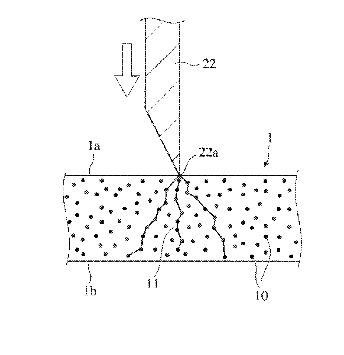
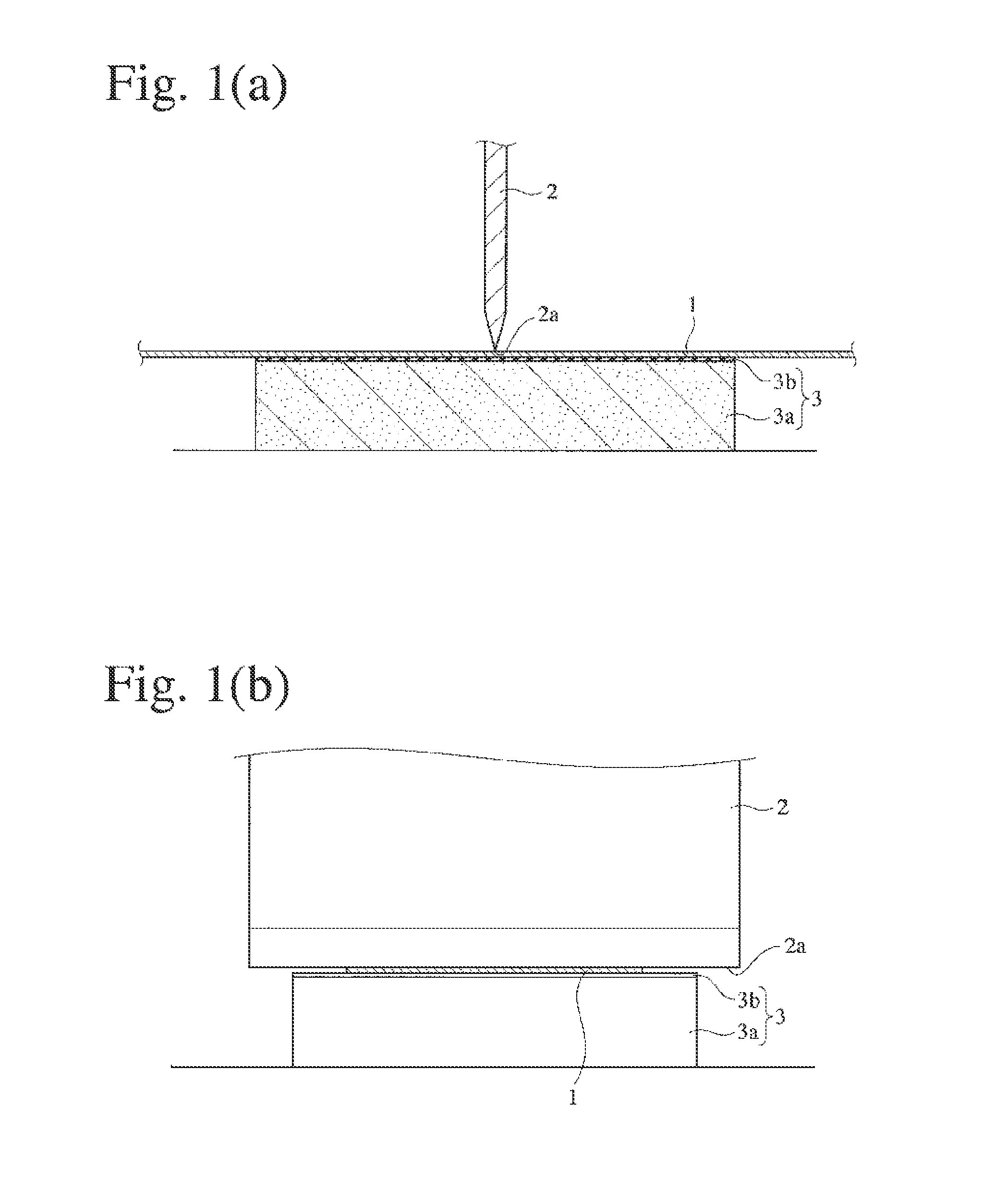
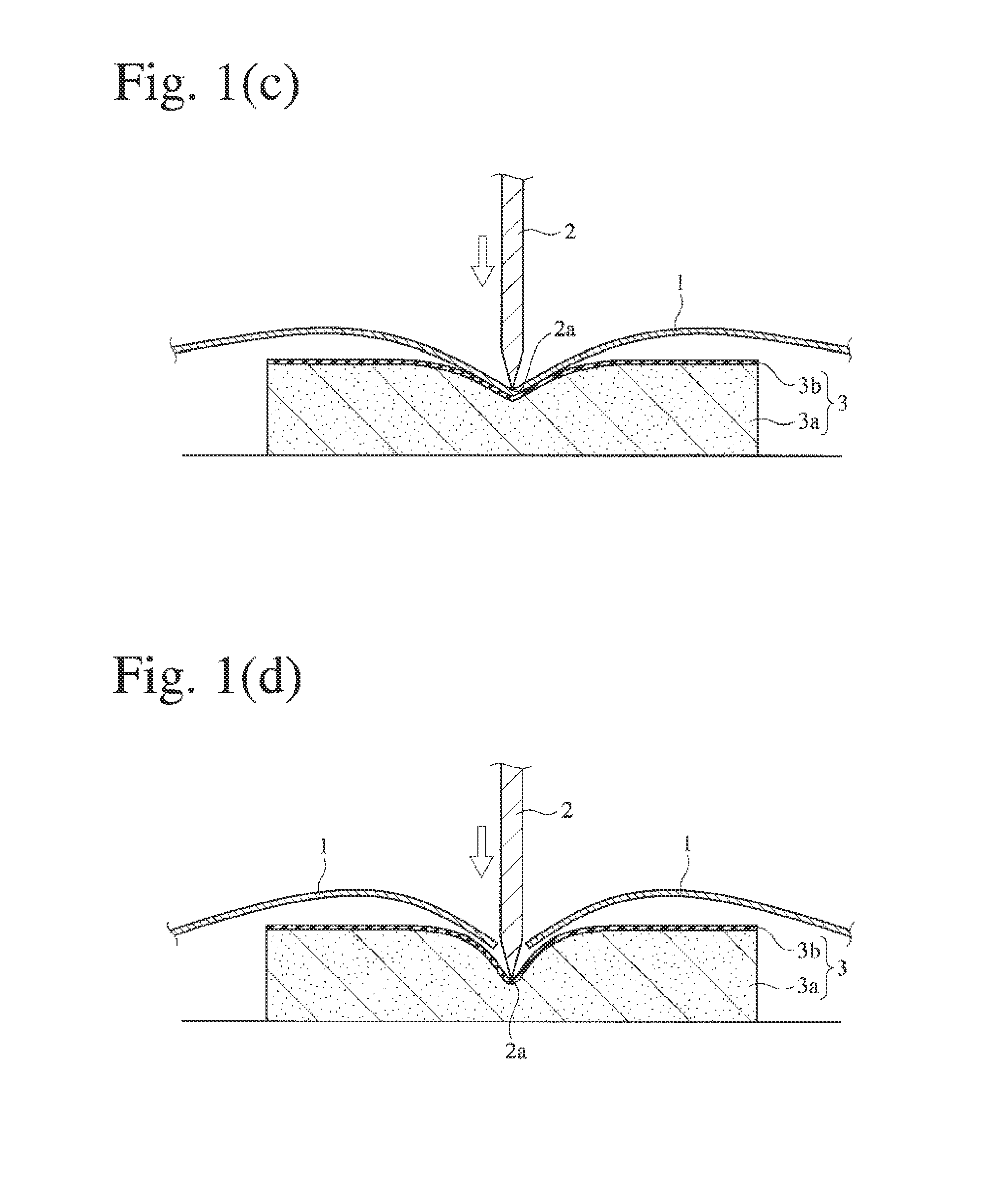
This patent describes a new type of ultrafine-crystalline alloy ribbon that can be easily and securely cut along a straight line without any sudden breaks or jagged edges. The ribbon has a unique structure, where ultrafine crystal grains are precipitated on a soft base. By using a cutter blade to bend the ribbon and press it sharply over its entire length, it can be fracture-cut along the blade with very smooth and straight lines. This technology can be used to create nanocrystalline, soft magnetic alloy ribbons that can be used in magnetic devices.

Problems solved by technology

Silicon steel is inexpensive and has a high magnetic flux density, but it suffers large core loss at high frequencies, and it cannot easily be made thin.
Co-based, amorphous, soft magnetic alloys are expensive and have as low saturation magnetic flux densities as 1 T or less, providing large parts when used for high-power applications.
In addition, because of thermal instability, the Co-based, amorphous, soft magnetic alloys suffer core loss increasing with time.
Fe-based, amorphous, soft magnetic alloys have as low saturation magnetic flux densities as about 1.5 T, with insufficiently low coercivity.
However, the alloy ribbons of WO 2007 / 032531 and WO 2010 / 084888 having structures in which ultrafine crystal grains are precipitated are extremely brittle with high hardness.
Also, even if they were tried to be broken along scratch lines formed by a glasscutter, etc., linear fracture would not be obtained along the scratch lines.
Further, a wider alloy ribbon having a structure in which ultrafine crystal grains are precipitated would be more difficult to be cut along a straight line without extremely jagged breakage, etc.
Further, magnetic devices such as wound cores, etc. formed by such alloy ribbons would not have stable quality (soft magnetic properties), and would suffer cracking from the jagged cut portion by a heat treatment, etc.

Method used


Image

  • Primary ultrafine-crystalline alloy ribbon and its cutting method, and nano-crystalline, soft magnetic alloy ribbon and magnetic device using it
  • Primary ultrafine-crystalline alloy ribbon and its cutting method, and nano-crystalline, soft magnetic alloy ribbon and magnetic device using it
  • Primary ultrafine-crystalline alloy ribbon and its cutting method, and nano-crystalline, soft magnetic alloy ribbon and magnetic device using it

Examples


examples 1 to 8

[0112]By a single roll method using a cooling roll made of a copper alloy, each alloy melt (1300° C.) having the composition shown in Table 1 was quenched in the air, and stripped from the roll at a ribbon temperature of 250° C. to obtain a primary ultrafine-crystalline alloy ribbon of 25 mm (Examples 1 to 5) and 50 mm (Examples 6 to 8) in width. To adjust the average grain size and volume fraction of ultrafine crystal grains, and the Vickers hardness Hv of the primary ultrafine-crystalline alloy ribbon, a gap between a nozzle and the cooling roll and a the peripheral speed of the roll (27-36 m / s) were changed during casting as shown in Table 1.

[0113]As shown in FIG. 5, the thickness and Vickers hardness Hv of each primary ultrafine-crystalline alloy ribbon were measured in each measurement point line 1 to 5. The average thickness was obtained by averaging the thickness values measured in the measurement point lines 1 to 5, and the thickness difference was difference between the max...

example 9

[0133]To investigate the relation between the percentage of notches and the gap without influence of the ribbon thickness, an alloy melt having a composition (atomic %) of Febal.Cu1.4Si4B14 was formed into primary ultrafine-crystalline alloy ribbons having a width of 25 mm and 50 mm, respectively, in the same manner as in Example 1 except for changing the gap as shown in Table 12, and changing the peripheral speed of the roll to provide the resultant ribbon with a constant thickness of 21 μm. It was confirmed that each ribbon had a structure in which ultrafine crystal grains having an average grain size of 30 nm or less were dispersed in a proportion of 5-30% by volume in an amorphous matrix. Next, each ribbon was measured with respect to hardness difference between a center portion and side portions, thickness difference in a transverse direction, and the percentage of notches generated when cutting was conducted by the linear pressing method of the present invention. The results a...

example 10

[0138]The primary ultrafine-crystalline alloy ribbon of Example 3 having a composition (atomic %) of Febal.Ni1Cu1.4Si4B14 was subjected to a high-temperature, short-time heat treatment comprising heating to 430° C. in 15 minutes and then keeping that temperature for 15 minutes, to obtain a nanocrystalline, soft magnetic alloy ribbon comprising fine crystal grains having an average grain size of 20 nm dispersed at a volume ratio of 45%. Using a B—H loop tracer, this nanocrystalline, soft magnetic alloy ribbon was measured with respect to a magnetic flux density B8000 at 8000 A / m (substantially equal to a saturation magnetic flux density Bs), a magnetic flux density B80 at 80 A / m, and coercivity Hc. As a result, B8000 was 1.81 T, B80 / B8000 was 0.93, and Hc was 7 A / m.


PUM

PropertyMeasurementUnit
Fractionaaaaaaaaaa
Fractionaaaaaaaaaa
Thicknessaaaaaaaaaa

Abstract

A method for cutting a primary ultrafine-crystalline alloy ribbon having a structure in which ultrafine crystal grains having an average grain size of 30 nm or less are dispersed in a proportion of 5-30% by volume in an amorphous matrix, comprising placing the ribbon on a soft base deformable to an acute angle by local pressing, bringing a cutter blade into horizontal contact with a surface of the ribbon, and pressing the cutter to the ribbon to apply uniform pressure thereto, thereby bending the ribbon along a cutter blade edge to brittly fracture-cut the ribbon.

Description

FIELD OF THE INVENTION[0001]The present invention relates to a primary ultrafine-crystalline alloy ribbon which can stably be cut linearly, a method for linearly cutting the primary ultrafine-crystalline alloy ribbon by brittle fracture, a nanocrystalline, soft magnetic alloy ribbon having excellent soft magnetic properties with a smoothly cut portion substantially free from jagged fracture and cracks, and a magnetic device formed thereby.BACKGROUND OF THE INVENTION[0002]Soft magnetic materials used for various reactors, choke coils, magnetic pulse power devices, transformers, magnetic cores for motors and power generators, current sensors, magnetic sensors, antenna cores, electromagnetic-wave-absorbing sheets, etc. include silicon steel, ferrite, Co-based, amorphous, soft magnetic alloys, Fe-based, amorphous, soft magnetic alloys and Fe-based, fine-crystalline, soft magnetic alloys, etc. Silicon steel is inexpensive and has a high magnetic flux density, but it suffers large core lo...

Claims


Application Information

Patent Timeline
IPC IPC(8): H01F1/153C22C45/02B26F3/00
CPCY10T225/10B22D11/001H01F1/15333C21D6/00C22C45/02C21D2201/03C22C33/003C21D2221/01C21D8/1211C21D2261/00C21D2221/02B22D11/0611C22C45/00B22D11/06B26F3/00H01F1/15308
Inventor OHTA, MOTOKIYOSHIZAWA, YOSHIHITO
Owner HITACHI METALS LTD
Learn More