Method for producing ceramic honeycomb body

a honeycomb body and ceramic technology, applied in ceramics, manufacturing tools, other domestic objects, etc., can solve the problems of insufficient strength of green bodies, failure to obtain predetermined strength after sintering, low strength, etc., and achieve the effect of low yield and little breakag

Active Publication Date: 2018-05-08
HITACHI METALS LTD
View PDF34 Cites 1 Cited by
  • Summary
  • Abstract
  • Description
  • Claims
  • Application Information

AI Technical Summary

Benefits of technology

[0010]Accordingly, an object of the present invention is to provide a method for producing a ceramic honeycomb body with a high yield, suffering little breakage during removing its peripheral portion by machining with a lathe.DISCLOSURE OF THE INVENTION
[0026]feeding the tool along the rotating ceramic honeycomb body from the first end surface toward the second end surface, to remove the peripheral portion by machining up to a position of 1 mm or more from the second end surface, stopping the feeding of the tool with an unmachined peripheral portion left on the side of the second end surface, and stopping the rotation of the ceramic honeycomb body;
[0032]feeding the tool along the rotating ceramic honeycomb body from the first end surface toward the second end surface, to remove the peripheral portion by machining up to a position of 1 mm or more from the second end surface, stopping the feeding of the tool with an unmachined peripheral portion left on the side of the second end surface, and causing the tool to retreat from the ceramic honeycomb body; and

Problems solved by technology

When as large a ceramic honeycomb structure as having an outer diameter of 150 mm or more and a length of 150 mm or more, or a ceramic honeycomb structure comprising cell walls as thin as 0.2 mm or less is produced, a green body does not have sufficient strength, suffering such problems as the deformation of cell walls near a peripheral layer by its own weight when extruded, and failure to obtaining predetermined strength after sintering.
However, a ceramic honeycomb body used for cleaning an exhaust gas generally has a cell structure constituted by porous cell walls, with low strength because of high porosity.
Also, when the ceramic honeycomb body is sintered, its strength is reduced because a binder is removed from the green body, breakage occurs more easily.
Further, when the ceramic honeycomb body is chucked for machining, a portion not machined because of chucking should be cut off, resulting in a low yield.

Method used


Image

  • Method for producing ceramic honeycomb body
  • Method for producing ceramic honeycomb body
  • Method for producing ceramic honeycomb body

Examples


example 1

[0123](a) Production of Ceramic Honeycomb Body

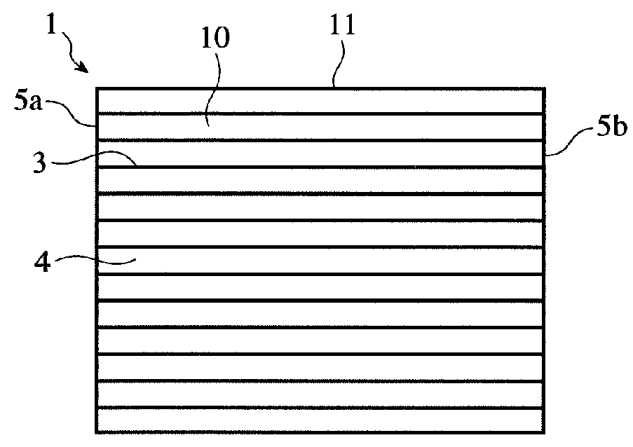
[0124]Kaolin powder, talc powder, silica powder and alumina powder were mixed to form a cordierite-forming material powder comprising 50% by mass of SiO2, 36% by mass of Al2O3 and 14% by mass of MgO, and this material powder was sufficiently dry-mixed with 8% by mass in total of methylcellulose and hydroxypropyl methylcellulose as a binder, a lubricant, and 7.0% by mass of foamed resin (average particle size: 40 μm) as a pore-forming material, and then fully blended with water to prepare a plasticized, moldable ceramic material. This moldable ceramic material was extruded, cut to a predetermined length to produce a honeycomb-structured green body having an outer diameter of 125 mm and a length of 150 mm, and dried for 20 minutes in a microwave-drying furnace to obtain a dried ceramic honeycomb body.

[0125](b) Removal of Peripheral Portion by Machining

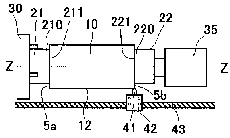
[0126]Using a lathe 30 (lathe A) shown in FIGS. 2(a) and 2(b), a peripheral portion 12 of...

examples 2-7

[0144]A dried ceramic honeycomb body 10 was produced in the same manner as in Example 1, and a peripheral portion 12 was removed from the dried ceramic honeycomb body 10 by machining with a lathe 30 (lathe B) shown in FIGS. 3(a) and 3(b) in the same manner as in Example 1, except for changing the abutting portions 210, 220 and the machining conditions (circumferential speed and feed rate) as shown in Table 1. The lathe B used herein was the same as the lathe A used in Example 1, except that abutting portions 210, 220 as separate members were threadably attached to the fixing jigs 21, 22, so that abutting portions 210, 220 were exchangeable. After the completion of machining, the same evaluation as in Example 1 was conducted, and sintering and the application of a coating material to the peripheral surface were conducted in the same manner as in Example 1 to produce a ceramic honeycomb structure.

examples 8-10

[0145]A dried ceramic honeycomb body 10 was produced in the same manner as in Example 1, and this dried body was sintered by an 8-day schedule having the highest temperature of 1410° C. in a sintering furnace, to obtain a sintered ceramic honeycomb body 10. A peripheral portion 12 of this sintered ceramic honeycomb body 10 was removed by machining in the same manner as in Examples 2-7, except for changing the abutting portions 210, 220 and the machining conditions (circumferential speed and feed rate) as shown in Table 1. The abutting member used in Example 9 had a rectangular cross section [see FIG. 5(c)], and the abutting member used in Example 10 had a hexagonal cross section [see FIG. 5(d)]. After the completion of machining, the same evaluation as in Example 1 was conducted, and sintering and the application of a coating material to the peripheral surface were conducted in the same manner as in Example 1, to produce a ceramic honeycomb structure.


PUM

PropertyMeasurementUnit
height Rzaaaaaaaaaa
circumferential speedaaaaaaaaaa
height Rzaaaaaaaaaa

Abstract

A method for producing a ceramic honeycomb body having large numbers of longitudinal cells partitioned by cell walls, with its peripheral portion removed by machining, includes rotatably holding the ceramic honeycomb body on a main axis of a lathe, and rotating the ceramic honeycomb body around the main axis, to remove its peripheral portion by machining with a tool; the lathe comprising a first fixing jig on the main axis, and a second fixing jig substantially opposing the first fixing jig; each of the first and second fixing jigs having an abutting end portion opposing each other, the abutting end portion having a smaller outer shape than that of the end surface of the ceramic honeycomb body, and the abutting portion having a substantially flat abutting end surface perpendicular to the main axis.

Description

CROSS REFERENCE TO RELATED APPLICATIONS[0001]This application is a National Stage of International Application No. PCT / JP2013 / 058752 filed Mar. 26, 2013 (claiming priority based on Japanese Patent Application No. 2012-083561, filed Apr. 2, 2012), the contents of which are incorporated herein by reference in their entirety.FIELD OF THE INVENTION[0002]The present invention relates to a method for producing a ceramic honeycomb body for constituting ceramic honeycomb structures or ceramic honeycomb filters used for removing toxic materials from an exhaust gas discharged from automobile engines, etc.BACKGROUND OF THE INVENTION[0003]To remove toxic materials from exhaust gases discharged from automobile engines, etc., a ceramic honeycomb structure 1 as shown in FIG. 1 is used for an exhaust-gas-cleaning catalyst converter comprising a ceramic honeycomb structure, and a particulate-matter-capturing filter.[0004]The production of a ceramic honeycomb structure comprises the steps of, for exa...

Claims


Application Information

Patent Timeline
Patent Type & Authority Patents(United States)
IPC IPC(8): B23Q1/70C04B41/50C04B41/00C04B41/85B28B11/12B23B5/12B28D1/16C04B111/00
CPCB23B5/12B28B11/12C04B41/85C04B41/5089C04B41/508C04B41/009B28D1/16C04B41/5024C04B41/53C04B35/00C04B38/0006C04B35/195Y10T82/10Y10T29/4962C04B2111/00793C04B2111/0081B23B2226/18B23B23/00B23B33/00B28B11/04C04B41/91
Inventor OKAZAKI, SHUNJI
Owner HITACHI METALS LTD
Why Eureka
Try Eureka