
Porous electrode substrate, method for producing the same, membrane electrode assembly, and polymer electrolyte fuel cell

a technology of electrode substrate and membrane electrode, which is applied in the direction of cell components, conductors, electrochemical generators, etc., can solve the problems of electrode substrate, high cost, complex production process, etc., and achieves the effects of small undulation, good handling, and small breakag

Inactive Publication Date: 2013-10-17
MITSUBISHI CHEM CORP
View PDF4 Cites 0 Cited by
  • Summary
  • Abstract
  • Description
  • Claims
  • Application Information

AI Technical Summary

Benefits of technology

[0016]The porous electrode substrate according to the present invention exhibits little breakage during compression, good handleability and small undulation, and has a sufficient gas permeability and a sufficient electroconductivity. The method for producing a porous electrode substrate according to the present invention is at low cost because it does not need a resin-binding step.

Problems solved by technology

However, the production process is complicated and a problem thereof is high cost.
Although, in order to reduce the cost, a porous electrode substrate is proposed which is obtained by forming a paper from oxidized short fibers, and thereafter firing the paper at a high temperature to carbonize the oxidized short fibers, since the oxidized short fibers shrink during firing, problems of the electrode substrate are the dimensional stability thereof and a large undulation (the state of the sheet cross-section being waved or the state of that being warped).
However, although the porous electrode substrate exhibits high mechanical strength, small undulation, sufficient gas permeability and sufficient electroconductivity, the problem thereof is high production cost.
Patent Literature 2 discloses a carbon fiber sheet having a thickness of 0.15 to 1.0 mm, a bulk density of 0.15 to 0.45 g / cm3, a carbon fiber content of 95% by mass or more, a compression deformation ratio of 10 to 35%, an electric resistivity of 6 mΩ or lower, and a degree of drape of 5 to 70 g. Although this method for producing the carbon fiber sheet can be at a low cost, since shrinkage during firing is large, problems that occur in the resulting porous electrode substrate include a large unevenness in the thickness and large undulation.
Although the porous electrode substrate can be produced at a low cost, since there is little entanglement between the carbon fibers and the acrylic pulp fibers during the process of forming the sheet, handling the porous electrode substrate is difficult.

Method used


Image

  • Porous electrode substrate, method for producing the same, membrane electrode assembly, and polymer electrolyte fuel cell
  • Porous electrode substrate, method for producing the same, membrane electrode assembly, and polymer electrolyte fuel cell

Examples


example 1

[0048]As short carbon fibers (A), PAN-based carbon fibers having an average fiber diameter of 7 μm and an average fiber length of 3 mm were prepared. As short carbon fiber precursors (b) having an average diameter of 5 μm or lower, acrylic short fibers having an average fiber diameter of 4 μm and an average fiber length of 3 mm (trade name: D122, made by Mitsubishi Rayon Co., Ltd.) were prepared. Further as an organic polymer compound, polyvinyl alcohol (PVA) short fibers having an average fiber length of 3 mm (trade name: VBP105-1, made by Kuraray Co., Ltd.) were prepared.

[0049]At first, 100 parts of the short carbon fibers (A) were dispersed in water. When the short carbon fibers (A) were sufficiently and homogeneously dispersed, 83 parts of the acrylic short fibers and 53 parts of the PVA short fibers were added into the suspension and were homogeneously dispersed. Then, the dispersion liquid was manually spread in a planar shape to form a paper (having a length of 250 mm and hav...

examples 2 and 3

, and 11 to 13

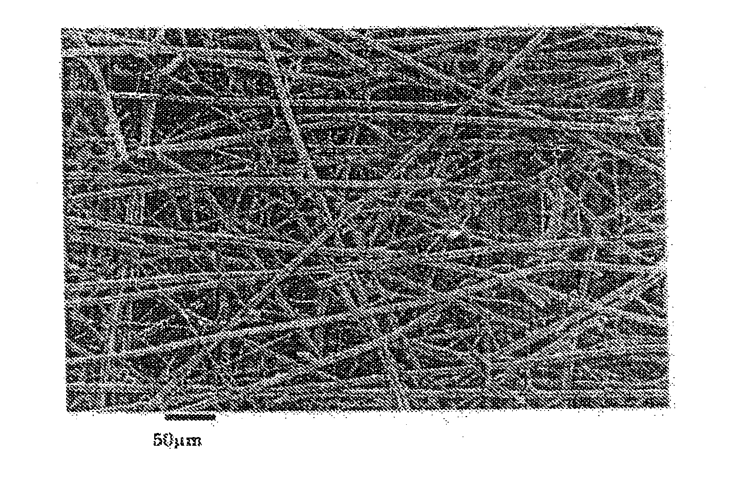
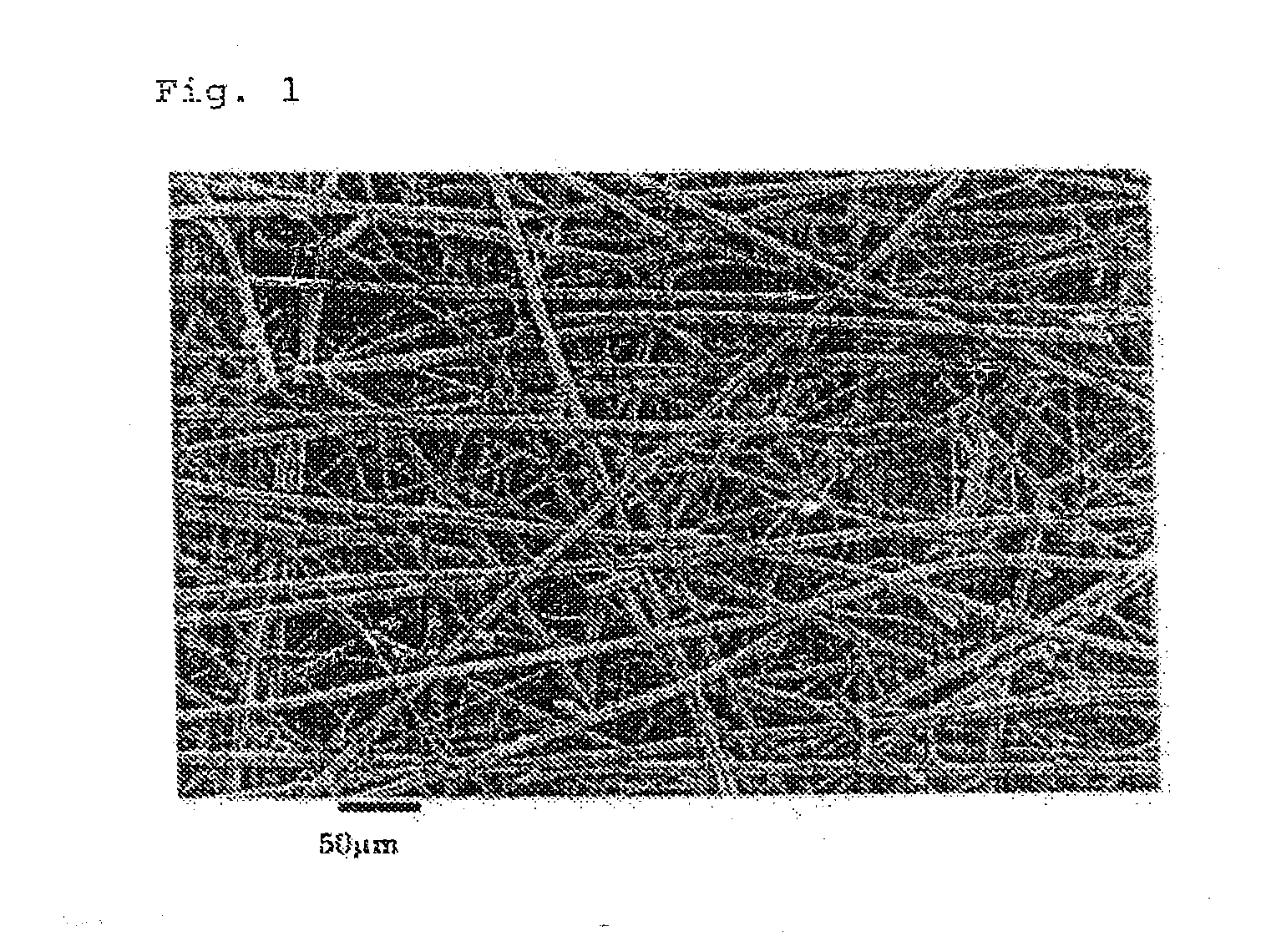
[0052]Porous electrode substrates were obtained as in Example 1, except for setting the amounts of the acrylic short fibers and the PVA short fibers that were used and the basis weights of the precursor sheet at values shown in Table 1. The porous electrode substrates exhibited almost no in-plane shrinkage during carbonization treatment, exhibited good handleability and small undulation of 2 mm or less, and had good air permeability, thickness and through-plane electric resistance. The planarly dispersed short carbon fibers (A) were joined via mesh-like carbon fibers (B). The evaluation results are shown in Table 1.

example 14

[0053]A porous electrode substrate was obtained as in Example 1, except for setting the amounts of the acrylic short fibers and the PVA short fibers that were used and the basis weight of the precursor sheet at values shown in Table 1, and subjecting one sheet of the precursor sheet to hot pressure forming. The porous electrode substrate exhibited almost no in-plane shrinkage during carbonization treatment, exhibited good handleability and small undulation of 2 mm or less, and had good air permeability, thickness and through-plane electric resistance. The planarly dispersed short carbon fibers (A) were joined via mesh-like carbon fibers (B). The evaluation results are shown in Table 1.


PUM

PropertyMeasurementUnit
diameteraaaaaaaaaa
thicknessaaaaaaaaaa
lengthaaaaaaaaaa

Abstract

Provided is a porous electrode substrate having high mechanical strength, good handling properties, high thickness precision, little undulation, and adequate gas permeability and conductivity. Also provided is a method for producing a porous electrode substrate at low costs. A porous electrode substrate is produced by joining short carbon fibers (A) via mesh-like of carbon fibers (B) having an average diameter of 4 μm or smaller. Further provided are a membrane-electrode assembly and a polymer electrolyte fuel cell that use this porous electrode membrane. A porous electrode substrate is obtained by subjecting a precursor sheet, in which short carbon fibers (A) and short carbon fiber precursors (b) having an average diameter of 5 μm or smaller have been dispersed, to carbonization treatment after optional hot press forming and optional oxidization treatment.

Description

TECHNICAL FIELD[0001]The present invention relates to a porous electrode substrate used in a polymer electrolyte fuel cell using a gas fuel and a liquid fuel, a membrane electrode assembly using the same, and a polymer electrolyte fuel cell.BACKGROUND ART[0002]Polymer electrolyte fuel cells are characterized by using a protonic conductive polymer electrolyte membrane, and are devices that provide an electromotive force by electrochemically reacting a fuel gas such as hydrogen with an oxidizing gas such as oxygen. The polymer electrolyte fuel cells can be utilized as private power generators and power generators for mobile bodies such as automobiles.[0003]Such a polymer electrolyte fuel cell has a polymer electrolyte membrane which selectively conducts hydrogen ions (protons). The fuel cell has two sets of gas diffusion electrodes and has a structure as described below. The gas diffusion electrode has a catalyst layer which contains, as a main component, a carbon powder which support...

Claims


Application Information

Patent Timeline
Patent Type & Authority Applications(United States)
IPC IPC(8): H01M4/86
CPCH01M4/8605D04H1/4242D21H13/50D21H15/02D04H1/43835D04H1/43838H01B1/122H01M4/926H01M8/0234H01M8/1007Y02E60/50Y10T29/49117Y10T428/30
Inventor SUMIOKA, KAZUHIROSAKO, YOSHIHIRO
Owner MITSUBISHI CHEM CORP
Learn More