Engineered Point Spread Function for Simultaneous Extended Depth of Field and 3D Ranging

a technology of extended depth of field and spread function, applied in the field of imaging, can solve the problems of slow process, many features inside thick objects may appear blurred, and the image depth of field is rapidly decreased, so as to reduce the effect of image nois

Inactive Publication Date: 2014-07-10
UNIV OF COLORADO THE REGENTS OF
View PDF15 Cites 22 Cited by
  • Summary
  • Abstract
  • Description
  • Claims
  • Application Information

AI Technical Summary

Benefits of technology

[0010]It is an object of the present invention to image a specimen with an extended depth of field, and simultaneously record 3D range information about the same specimen, while reducing the effects of image noise.
[0017]An embodiment of the present invention returns to the basic compound microscope design and simply manipulates the wavefront of the imaging beam as it exits the microscope objective to increase its information content. This is accomplished by inserting a custom designed optical element, called a waveplate, into a slot in the microscope objective lens turret (such as one designed to hold a DIC prism slider). The novel waveplate design modifies the wavefront to create a PSF that is slightly blurred, and focus invariant over an extended depth. The blur introduced by the waveplate is then removed by a single, digital filtering algorithm to restore fine detail to all image features within the focus invariant PSF region. This embodiment extends the DOF of a high NA objective lens by up to 10-12 times so that all features throughout the cell volume appear sharply focused in a single recorded image. By simultaneously recording a different focal region of the wavefront modified by the same waveplate, the invention acquires a highly accurate depth map that provides the ability to locate specimen features to within 75 nm or better. Thus, after batch processing the image pairs, full 3D animations can be displayed of live cell processes that were recorded at speeds more than an order of magnitude faster than are possible with any existing commercial biological microscope (e.g. at 10-20 ms per 3D image time point instead of 1-2 sec per multi-focal image stack). This batch processing may be accomplished, for example, using a linear deconvolving digital filter or a nonlinear neural network algorithm.
[0020]The EDF image results in a modulation transfer function having no zeroes over a desired depth of focus. The EDF image is generally deconvolved, and noise is removed.

Problems solved by technology

Strict adherence to these design criteria results in well-known tradeoffs or compromises in objective lens performance, specifically: (1) increasing lateral resolution (i.e. increasing NA) causes a rapid decrease in image depth of field so that many features inside thick objects may appear blurred if they fall above or below the plane of best focus, and (2) each single image is a two-dimensional (2D) projection in which the 3D positions of biological features inside the specimen volume are lost.
However, this process is slow, usually requiring a minimum of 1-2 seconds to acquire each image stack which can lead to increased fluorophore bleaching as well as motion blur of fast moving cell features.
Other schemes, such as multi-focal plane illumination designs that try to speed up the depth scanning process, introduce the possibility of alignment errors and require expensive optoelectronics.
However, the wavefront coding approach was so severely limited by noise and image reconstruction artifacts that it proved to be an unviable option for high-resolution, extended depth of field (EDF) biological microscopy.
A further limitation of these microscopes is that the only way they address the problem of reducing image noise is by using very expensive, low-noise detectors such as EMCCD or CMOS cameras, or photomultiplier tubes in the case of confocal point scanning systems.
These usually appear as randomly scattered bright image pixels arising from detector electronics and shot noise, and are particularly problematic in light starved applications such as when observing weakly fluorescing live-cell structures.

Method used


Image

  • Engineered Point Spread Function for Simultaneous Extended Depth of Field and 3D Ranging
  • Engineered Point Spread Function for Simultaneous Extended Depth of Field and 3D Ranging
  • Engineered Point Spread Function for Simultaneous Extended Depth of Field and 3D Ranging

Examples


Embodiment Construction

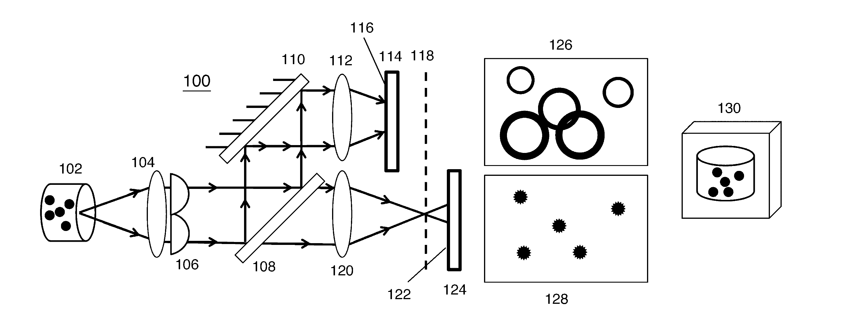
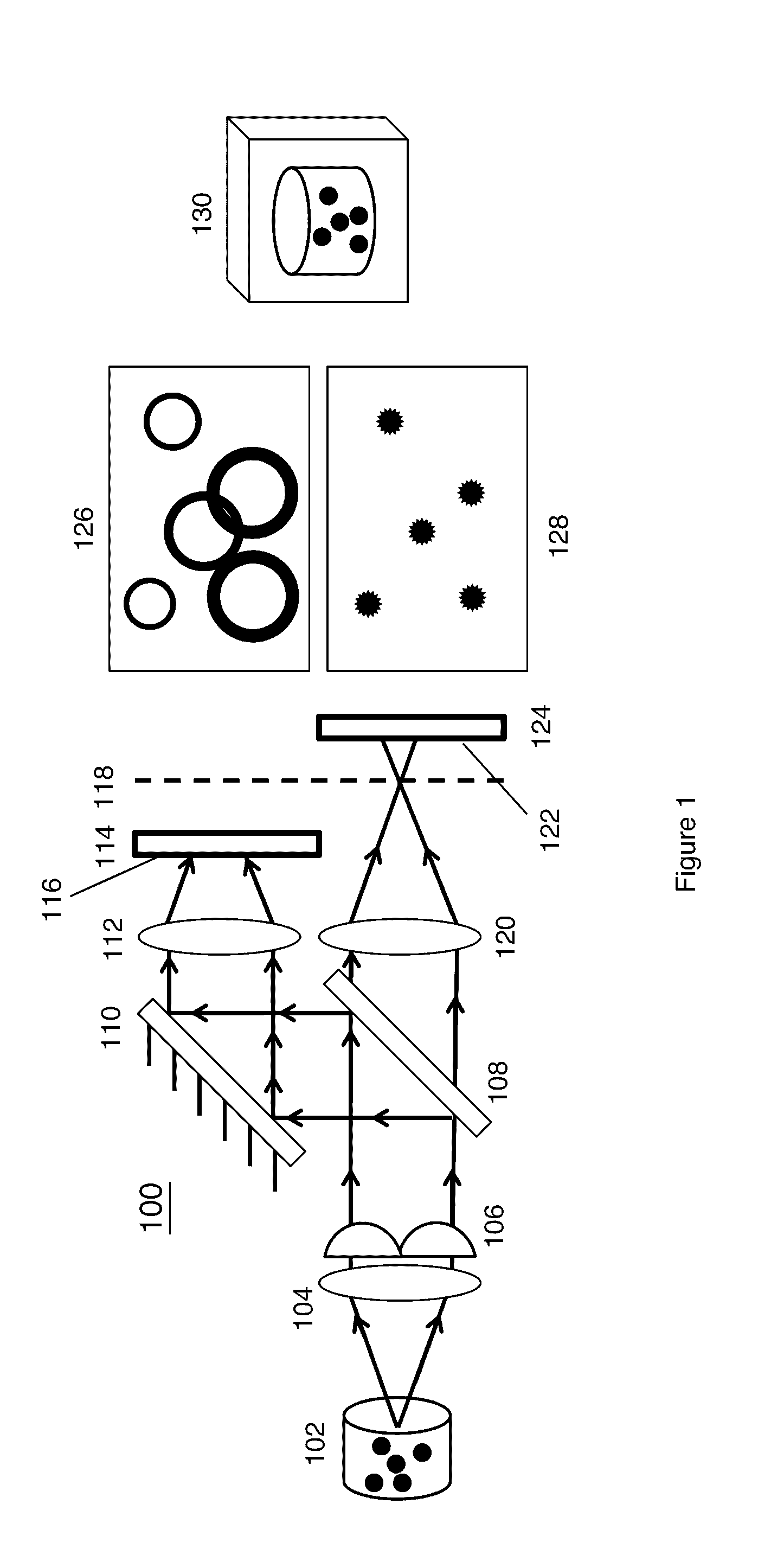
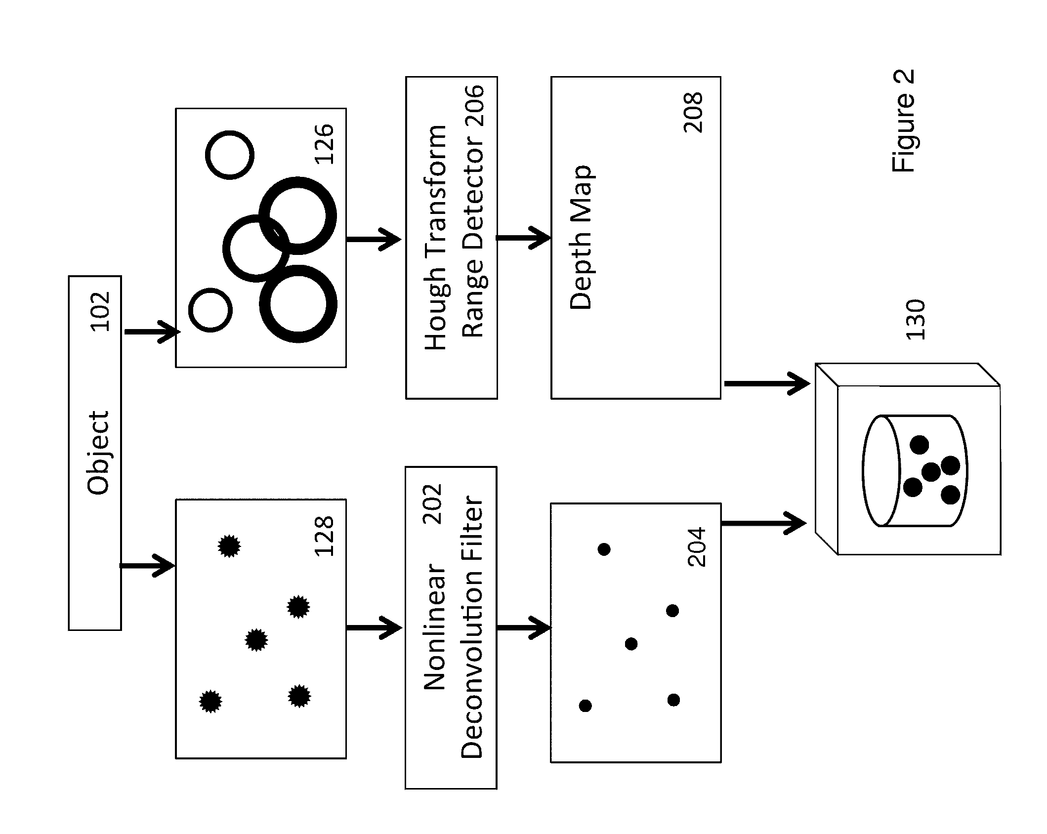
[0035]FIG. 1 is a schematic block diagram illustrating apparatus 100 accomplishing extended depth of field and ranging according to the present invention. Apparatus 100 might be a basic compound microscope design, with two additions: waveplate 106 and a beam-splitter 108 / mirror 110 combination for forming two images 126, 128 at planes 116 and 122.

[0036]Object 102 might comprise a sample containing elements at various depths. It is shown here as several points, for clarity in the following explanations. Light from object 102 is passed through lens 104 and waveplate 106. Waveplate 106 is located (for example) at the back aperture plane of the microscope objective, and causes the image to have a relatively focus invariant point spread function on one side of a plane of best focus, while causing the point spread function shapes to vary with range on the other side of the plane of best focus (for example, points might generate rings whose circumferences vary as a function of range or dep...


PUM


Abstract

Optical systems utilize waveplates to simultaneously encode information for increasing image depth of field and for providing a depth map of the imaged object or sample. These waveplates are configured to result in a focus-invariant point spread function in one focal region, and to result in point spread functions that vary as a function of range within the imaged object in a different focal region. For example, a basic compound microscope might have a specially shaped waveplate inserted at the back aperture plane of the microscope objective to manipulate the phase of the wavefront. An image formed on one side of the plane of best focus is focus invariant, and is brought into focus by a restoring algorithm. An image formed on the other side of the plane of best focus captures point spread functions comprising rings that vary with depth within the imaged object.

Description

BACKGROUND OF THE INVENTION[0001]1. Field of the Invention[0002]The present invention relates to imaging that accomplishes extended depth of field and 3D ranging simultaneously. In particular, the present invention accomplishes such ranging utilizing an engineered point spread function and forming dual images for processing.[0003]2. Discussion of Related Art[0004]Breakthroughs in optoelectronic technologies over the past few decades have led to an explosion of new microscope configurations for addressing specific biological problems. However, these microscopes still have significant shortcomings that, if overcome, could provide biologists with the ability to conduct a greater range of live-cell imaging investigations. Specifically, the ability to create images of sharply focused fine structure throughout the entire 3D cell volume at video rates or faster is still needed. Also needed is a way to reduce the ubiquitous noise common to low light imaging applications, such as in live-cel...

Claims


Application Information

Patent Timeline
Patent Type & Authority Applications(United States)
IPC IPC(8): H04N13/02
CPCH04N13/025H04N13/0271G06T2207/10052G06T2200/21G06T7/0069G06T7/571H04N13/236H04N13/25H04N13/271
Inventor COGSWELL, CAROL J.CORMACK, ROBERT H.ZAHREDDINE, RAMZI N.
Owner UNIV OF COLORADO THE REGENTS OF
Why Eureka
Try Eureka