

Copper-based alloy wire and methods for manufaturing the same
a technology of copper-based alloy wires and manufacturing methods, applied in the direction of vacuum evaporation coatings, basic electric elements, coatings, etc., can solve the problems of generating electron migration, local coarse grain formation, negatively affecting bonding strength,
- Summary
- Abstract
- Description
- Claims
- Application Information
AI Technical Summary
Benefits of technology
Problems solved by technology
Method used
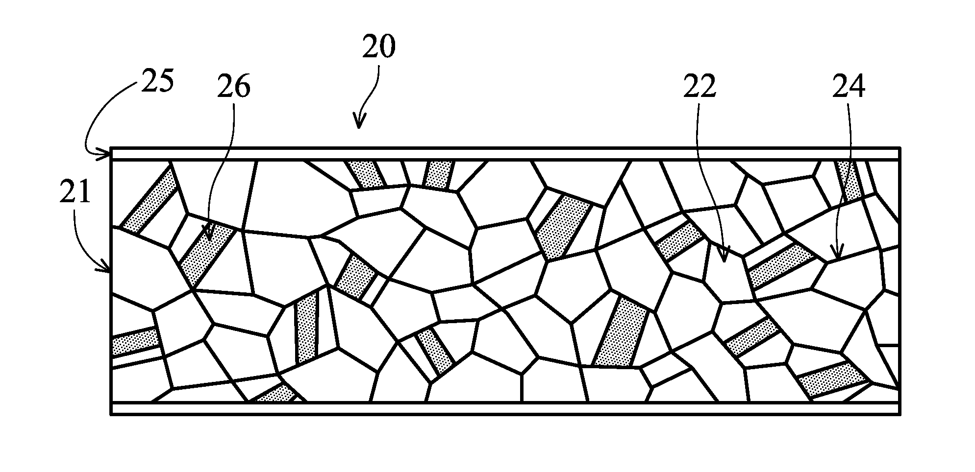
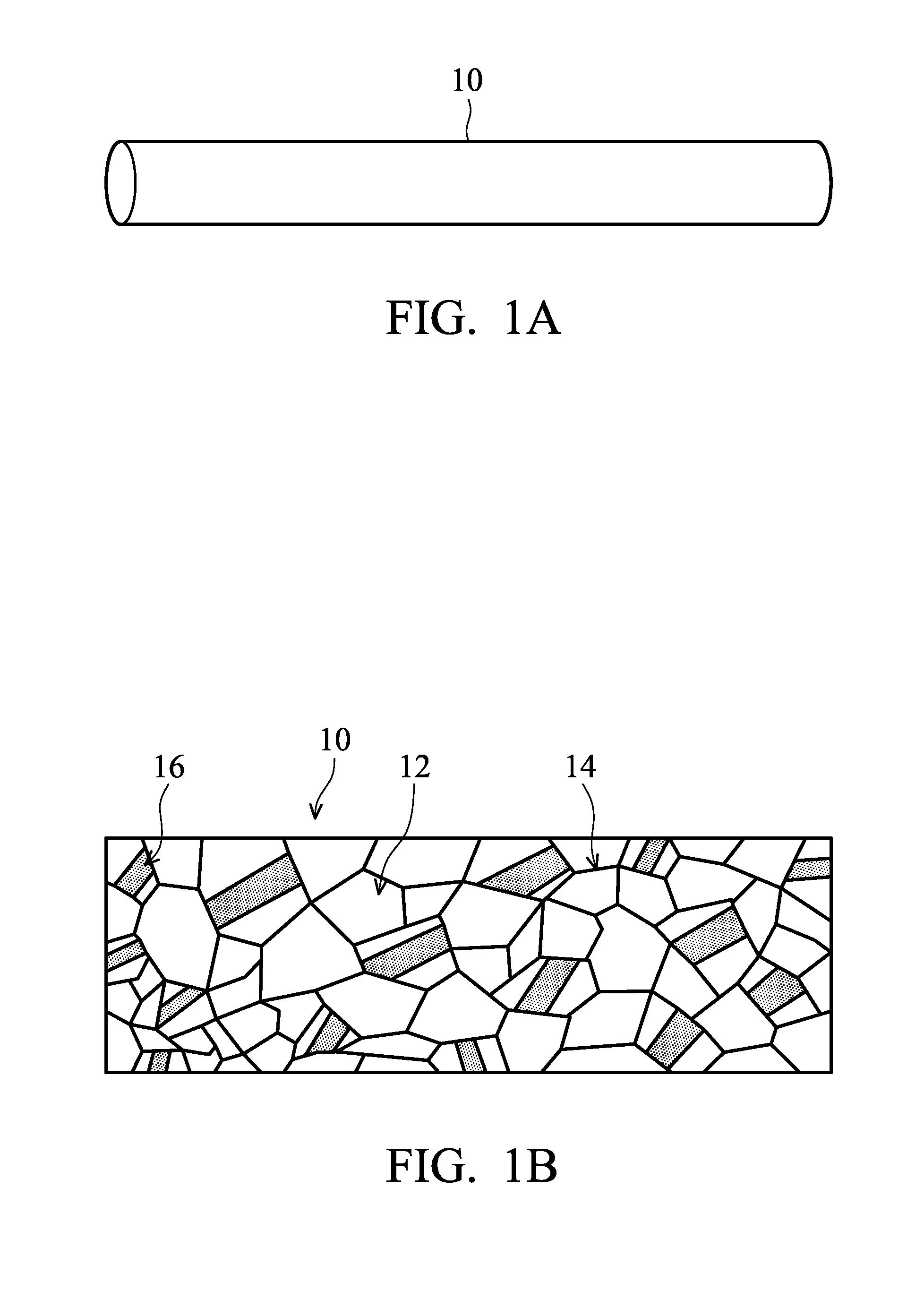
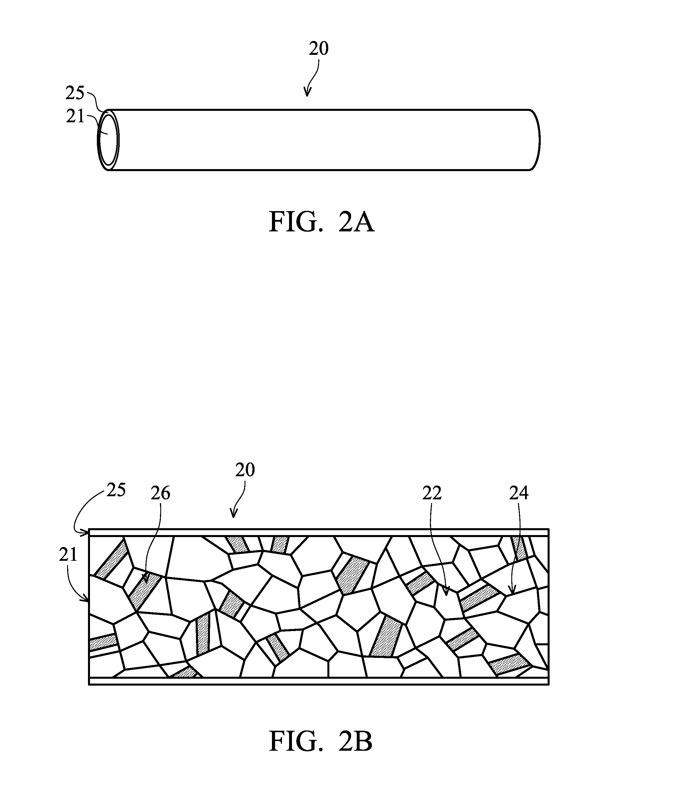
Image

Examples
example 1
[0071]A copper-1 wt % palladium alloy was smelted by high-frequency electric smelting, followed by continuous casting to form a pre-formed wire with a wire diameter of 6 mm. An initial wire-drawing step was then performed on the pre-formed wire to form an in-process wire with a wire diameter of 1 mm. A gold film of 10 μm thick was plated on the surfaces of the in-process wire by electroplating. The in-process wire became an intermediate wire with a wire diameter of 22.6 μm after a plurality of alternative steps of wire drawing elongation and annealing treatment, followed by performance of the second-last step of wire drawing elongation, becoming an intermediate wire with a wire diameter of 20 μm. Next, the intermediate wire was annealed at 530° C. for 1.5 seconds, followed by performance of the last step of wire drawing elongation, becoming a final wire with a wire diameter of 17.5 μm. Finally, the last step of the annealing treatment was performed on the fine wire at an annealing t...
example 2
[0077]A copper-1 wt % gold-2 wt % palladium alloy was smelted by high-frequency electric smelting, followed by continuous casting to form a pre-formed wire with a wire diameter of 6 mm. The pre-formed wire became an intermediate wire with a wire diameter of 22.6 μm after a plurality of alternative steps of wire drawing elongation and annealing treatment, followed by performance of the second-last step of wire drawing elongation, becoming an intermediate wire with a wire diameter of 20 μm. Next, the intermediate wire was annealed at 530° C. for 1.5 seconds, followed by performance of the last step of wire drawing elongation, becoming a final wire with a wire diameter of 17.5 μm. Finally, the last step of the annealing treatment was performed on the final wire at an annealing temperature of 570° C. for 4.8 seconds. Completing the last step of the annealing treatment, the final wire was wound, and then an alloy wire product for wire bonding was complete. Moreover, all the described ann...
PUM
| Property | Measurement | Unit |
|---|---|---|
| Temperature | aaaaa | aaaaa |
| Temperature | aaaaa | aaaaa |
| Length | aaaaa | aaaaa |
Abstract
Description
Claims
Application Information