
Method for Estimating State of Charge for Lithium-Ion Batteries

a lithium-ion battery and state estimation technology, applied in the field of lithium-ion batteries, can solve the problems of difficult analysis of performance, impracticality of estimation for many applications, drift of coulomb counting, etc., and achieve the effect of ensuring stability of estimation error

Inactive Publication Date: 2014-07-31
MITSUBISHI ELECTRIC RES LAB INC
View PDF0 Cites 50 Cited by
  • Summary
  • Abstract
  • Description
  • Claims
  • Application Information

AI Technical Summary

Benefits of technology

The patent text describes a method for estimating the state of health (SoC) and parameters of an electrochemical battery using an electrochemical single particle model (SPM). The method involves identifying partial model parameters from an open circuit voltage-SoC data using a nonlinear optimization problem, and then estimating the SoC and the rest of the model parameters using an iterated extended Kalman filter or a nonlinear adaptive estimator. The nonlinear adaptive estimator overcomes nonlinearity in the battery model, providing a convergent estimation of the SoC even with a large deviation in initial SoC. The main technical effect is the improved accuracy and efficiency in estimating the SoC and parameters of electrochemical batteries.

Problems solved by technology

The estimation requires the battery to be disconnected from a load making the estimation impractical for many applications.
Coulomb counting can also be subject to drift due to cumulative integration errors, and noise corruption.
These methods are intuitive and the performance is difficult to analyze.
The disclosed method has limitations, such as linearization-based technique is used thus difficult to ensure the quality of the estimation of the SoC.
However, such models have a complex structure based on partial differential equations (PDEs), often necessitating model simplification, or reduction.
Various of existing estimation approaches suffer from the incapability to estimate the SoC with guaranteed convergence, which means the quality of the estimated SoC is not ensured.

Method used


Image

  • Method for Estimating State of Charge for Lithium-Ion Batteries
  • Method for Estimating State of Charge for Lithium-Ion Batteries
  • Method for Estimating State of Charge for Lithium-Ion Batteries

Examples


Embodiment Construction

Battery Model

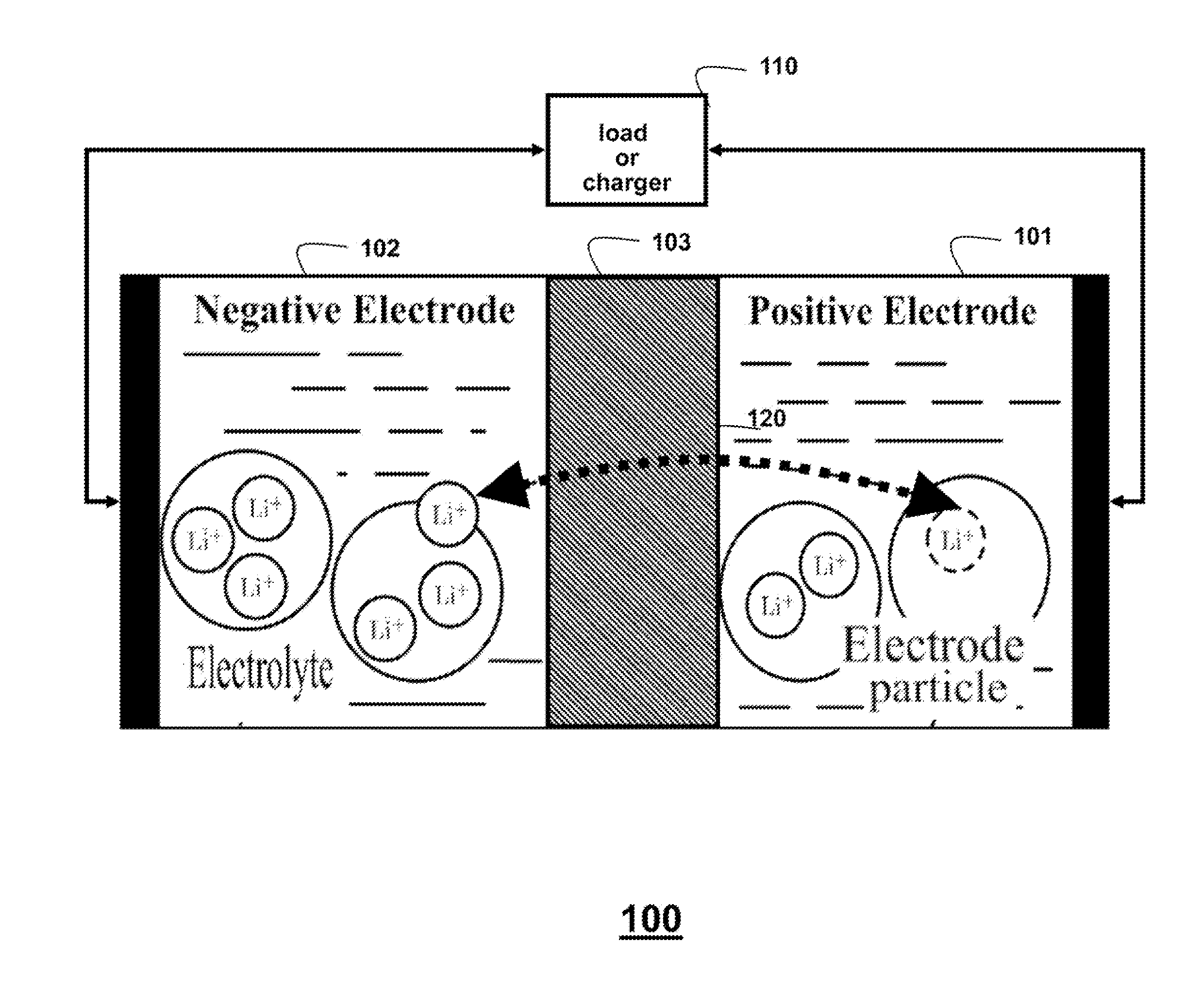
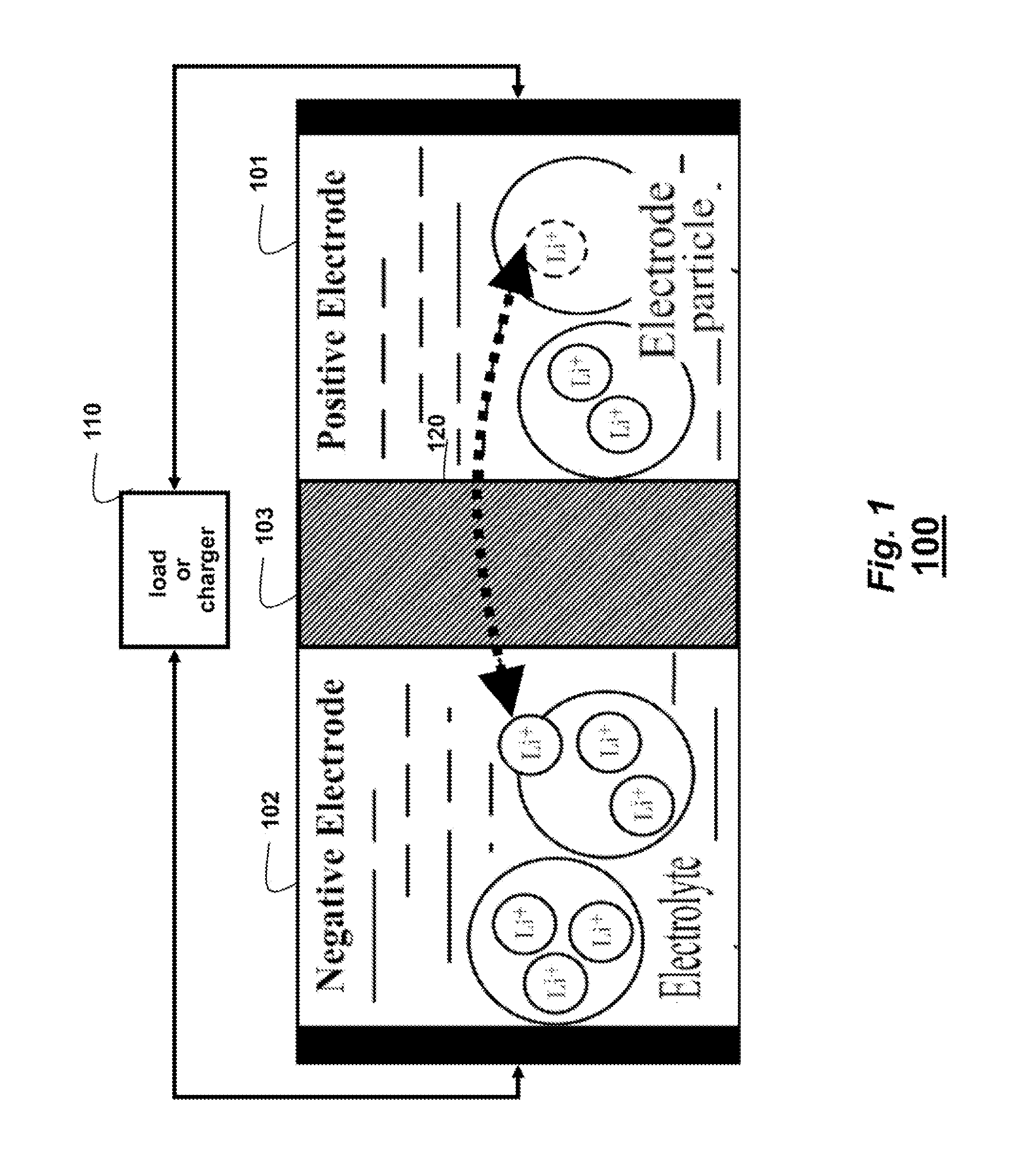
[0019]FIG. 1 shows a schematic of a lithium-ion (Li+) battery 100 that can use embodiments of the invention. A positive electrode 101 is e.g., a metal oxide, a polyanion, or spinel. Small solid particles of the compounds are compressed to provide a porous structure. A negative carbon electrode 102, which usually contains graphite particles, is also porous. The interstitial pores at both electrodes provide intercalation space, where the Li+ ions can be stored. The non-aqueouse electrolyte contains free ions and is electrically conductive. A separator 103 is arranged between the electrodes. The separator enables the exchange of Li+ ions from one side to the other, without passing electrons. Thus, electrons must either flow through a load or charger 110.

[0020]When the battery is charging, the Li+ ions are extracted 120 from the particles at the positive electrode into the electrolyte, driven by a reaction at a solid particle-electrolyte interface, and the particles at the ...


PUM


Abstract

A state of charge (SoC) a lithium-ion (Li+) battery is estimated at a time instant by first constructing a model of the Li+ battery based on a single particle operation. The model describes a relationship between the SoC, a charge current, a discharge current, and an output voltage. Using a nonlinear optimization, a function expressing a relationship between the SoC and an open circuit voltage is determined. The relationship is based on off-line measurements of the charge current, the discharge current, and the open-circuit voltage. Then, the SoC and parameters of the model are estimated concurrently, wherein the SoC and the parameters are based on the model, the function, and on-line measurements of the charge current, the discharge current, and the output voltage.

Description

FIELD OF THE INVENTION[0001]This invention relates generally to lithium-ion batteries, and more generally to estimating a state of charge (SoC) and parameters for the batteries.BACK GROUND OF THE INVENTION[0002]Lithium-ion (Li+) batteries have a high energy density, wide temperature range, small size, superior power performance and durability, no memory effect, and no loss of charges when not in use when compared with other batteries. Battery management systems (BMS) can be used to monitor the battery status and regulate charging and discharging processes for real-time battery protection and performance improvement. The BMS can estimate a state of charge (SoC). The SoC is a ratio of the current capacity to the maximum capacity of the battery.[0003]Two conventional SoC estimation methods are voltage translation, and Coulomb counting. Voltage translation directly converts a measured voltage to an estimard SoC. Coulomb counting infers the SoC from open circuit voltage (OCV)-SoC data fo...

Claims


Application Information

Patent Timeline
Patent Type & Authority Applications(United States)
IPC IPC(8): H02J7/00
CPCH02J7/00G01R31/367G01R31/3842H01M10/0525Y02E60/10
Inventor WANG, YEBINFANG, HUAZHENSAHINOGLU, ZAFER
Owner MITSUBISHI ELECTRIC RES LAB INC
Learn More